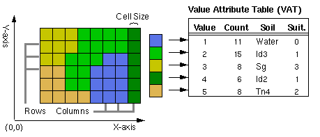
An Esri Grid is for storing raster data that defines geographic space as an array of equally sized square pixels (also known as cells) arranged in rows and columns. There are two types of grids depending on data type: integer and floating point.
Attributes for an integer grid are stored in a value attribute table (VAT). A VAT has one record for each unique value in the grid. The record stores the unique value and the number of pixels. The VALUE is an integer that represents a particular class or grouping of pixels. The COUNT is the number of pixels representing the value in the grid. For example, if 50 pixels have a value of 1 representing a forest, the VAT would show a VALUE = 1 and COUNT = 50 for each of the 50 pixels.
Learn more about raster dataset attribute tables

Floating-point grids do not have a VAT because the pixels in the grid can assume any value within a given range of values. The pixels in this type of grid do not fall neatly into discrete categories. The pixel value itself is the attribute that describes the location. For example, in a grid that represents elevation data in meters above sea level, a pixel with a value of 10.1662 indicates that the location is about 10 meters above sea level.
The range of data values that can be stored as grid values are as follows:
- Floating-point grids can store values from -3.4 x 1038 to 3.4 x 1038.
- Integer grids can store values from -2147483648 to 2147483647 (-231 to 231-1).
For integer grids, this information applies only to the VALUE item. An integer grid may have other items added to its VAT whose range of values depends on the item definition.
The coordinate system of a grid is the same as that of other geographic data. The rows and columns are parallel to the x- and y-axes of the coordinate system. Since each pixel within a grid has the same dimension as other pixels, the location and area covered by any pixel can be determined by its row and column. The coordinate system of a grid is thus defined by the pixel size, the number of rows and columns, and the x,y coordinate of the upper left corner. Grids also carry additional information, such as the coordinate system associated with the grid.
Caution:
As with most formats, a grid should not be named with spaces or any other special characters in its name. A multiple-band grid cannot have more than 9 characters in its file name, and a single-band raster dataset cannot have more than 13 characters.
Grid data structure
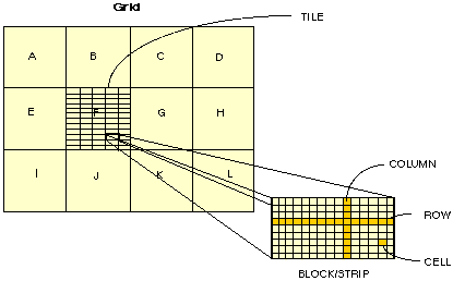
Grids are implemented using a tiled raster data structure, in which the basic unit of data storage is a rectangular block of pixels. Blocks are stored on disk in compressed form in a variable-length file structure referred to as a tile. Each block is stored as one variable-length record.
The size of the tile for a grid is based on the number of rows and columns in the grid at the time of creation. The upper limit on the size of a tile is set by the application, with an upper limit of 4,000,000 x 4,000,000 pixels. As a result, most grids used for GIS applications are automatically stored in a single tile. The spatial data for a grid is automatically split across multiple tiles if the size of the grid at the time of creation is larger than the upper limit for the size of a tile.
The blocked storage organization for grids supports both sequential and random spatial access to large raster datasets. The blocking structure imposes no restrictions on the joint analysis of grids. Tiles and blocks from different grids do not need to coincide in map space for joint analysis, and you can create and manipulate a grid as though it were a seamless raster of uniformly square pixels.
Grids use a run-length raster compression scheme that is adaptive at the block level. Each block is tested to determine the depth (bits per pixel) to be used for the block and to determine which storage technique (pixel by pixel or run length coded) is more efficient. The block is stored in the format that requires less disk space. The adaptive compression scheme is the optimal choice because of its ability to efficiently represent both homogeneous categorical data and heterogeneous continuous data while supporting joint analysis using both types of data. Single layer per-pixel operations, such as data reclassification, operate directly on data processes without decompression. Multilayer per-pixel operations on compressed input layers intersect data processes from the different layers and operate on the intersected processes. Single-layer per-neighborhood operations and multilayer per-pixel operations that mix compressed and uncompressed data expand processes into pixels and perform traditional pixel-by-pixel processing transparently.

The tile-block structure of a grid is also transparent to any application programs that access the spatial data in a grid. Programs that manipulate grids access the spatial data by setting a rectangular window defined in map coordinates.
Grid data storage
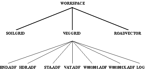
A grid is stored in a workspace. The grid is stored as a separate directory with associated tables and files that contain specific information about the grid. In an integer grid workspace, the following tables and files are found:
- BND table, which stores the boundary of the grid
- HDR file, which stores specific information describing the grid, for example, pixel resolution and blocking factor
- STA table, which contains statistics for the grid
- VAT table, which stores the attribute data associated with the zones of the grid
- LOG file, which monitors the activity that has occurred on the grid
- A tile file w001001.adf (q0x1y1), which stores the pixel data and the accompanying index file w001001x.adf (q0x1y1x) that indexes the blocks in the tile and the LOG files

If a grid is altered, the values and information contained in the files and tables are updated immediately.
BND table
A grid BND contains the boundary of the grid. The boundary is a rectangle that encompasses the pixels of a grid; it is stored in map coordinates. All grid BNDs are stored in double precision.
The minimum coordinates in the BND table are for the lower left corner of the lower left pixel in the grid. The maximum coordinates are for the upper right corner of the upper right pixel in the grid.
HDR file
The HDR is a binary file. Information stored in the file includes the pixel size, type of grid (integer or floating point), compression technique, blocking factor, and tile information.
STA table
The STA table is a table that contains statistical data about a grid. The minimum, maximum, mean, and standard deviation for the grid are stored as floating-point values in the STA table. You should not attempt to alter these values directly.
Because NoData represents an unknown value, NoData is not used in calculating the statistics in the STA table.
When a bilevel grid (containing only 0 and 1 values) is created, the STA table contains the value 0 for the mean and -1 for standard deviation. The standard deviation value -1 indicates that statistics have not been calculated for a grid.
A standard deviation value of -2 indicates that the grid contains only NoData pixels.
VAT table
The VAT is a table that stores attributes associated with the zones of a grid. Only integer grids have a VAT associated with them. Every VAT has at least two items, VALUE and COUNT. The VALUE item contains integer values that are used to distinguish the characteristics of one location from the other locations in a grid. All pixels that are assigned the same value contain the same characteristics and, therefore, belong to the same zone. COUNT is the number of pixels in a zone.
New items can be added to the VAT. The VALUE and COUNT items should not be changed, and the VAT must be kept sorted on the VALUE item.
Note:
Do not add new items before VALUE or COUNT.
Pixels containing NoData are not represented in the VAT.
Below is an example of a VAT:
Record	 VALUE     COUNT
 1        0       628872
 2        1       265043
 3        2       151150
 4        3      3185652
 5        4        79983
 6        5         4782
 7        6        74334
 8        7         8877
 9        8         1817
 10       9          491
 11      10          858
 12      11         8770
 13      12        28789
 14      13        72539
 15      14         3686
 16      15         3932
 17      16        13227
 18      17         1890
 19      18         1305
 20      19       427286
 21      20         6695
Tile files
The w001001.adf (q0x1y1) and w001001x.adf (q0x1y1x) files store the data and the index for the first, or base tile, in a grid. The upper limit on the size of a tile is large, and most grids are stored using a single tile. If additional tiles are used, they are automatically numbered based on their spatial relationship to the first tile. Tiles are implemented as variable-length binary files.
LOG file
The LOG file is an ASCII file that contains information about the creation and alteration of a grid. The LOG monitors the actions performed on the grid, but it does not contain every action performed with the grid. Since all grid operations result in a new grid, only grid commands, such as RENAME and COPY, can alter an existing grid and be entered into the LOG file. The LOG file can be accessed, like all ASCII files, through system commands or any text editor.
Storage limitations
The name of a grid is limited as follows:
- It cannot be stored using spaces or special characters.
- It cannot start with a number.
- It cannot be longer than 13 characters (a multiband grid is allowed up to 9 characters).
There is a limit to the number of files that can be stored in a directory for both coverages and grids. This total is approximately 10,000. Therefore, this limits the number of grids you can store in a workspace. For example, the following lists the theoretical maximum number of grid datasets that can be stored in a single workspace directory:
- Fewer than 5,000 floating point grids, or
- Fewer than 3,333 integer grids, with VATs (fewer than 5,000 if no VATs), or
- Fewer than 10,000 grid stacks
The preceding numbers are the theoretical maximums. If you have a process that will create interim grids (and therefore files in the workspace) these numbers will be less. Additionally, if you are storing a mix of files, such as grids and coverages, you will store fewer.
These numbers relate to the number of files in the grid folder that store information in the workspace. The limit is 9,999, but it’s not the total number of files in a workspace; it’s the number of files pointing to the files in the workspace. For each grid, there are two files in the grid’s folder pointing to files in the workspace: the BND (boundary) files and STA table (statistics) files (9999/2≈5000). When a grid has a VAT, this also points to files in the workspace, so the number that can be stored is reduced again (9999/3≈3333). A grid stack only has a single file, which points to the workspace (9999/1≈9999).
Stack
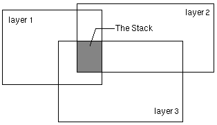
A stack consists of an ordered set of spatially overlapping grids (layers) treated as a single entity for multivariate analysis. Cluster analysis, classification, and principal component analysis all work on the layers in a stack.

A stack has the following characteristics:
- A set of layers with each layer corresponding to a grid
- A map extent, or BND
- A pixel size
- A data type
- A projection
Each layer specified in a stack has an index number indicating its order in the stack. The grids that make up a stack must be in the same workspace.
The boundaries of the input layers can overlap exactly, partially, or not at all, but only the area where layers overlap comprises the stack. The stack's BND is where the boundaries of its layers intersect. The computations of a multivariate analysis function occur on the overlapping area. If there is no common area between the input layers, the stack is empty and no computations occur.

The pixel size of a stack defaults to the coarsest layer in the stack.
You can combine any number of data types (real or integer) of the input grids in a stack; however, before applying a multivariate technique, you should be aware of what the values represent, whether categorical or continuous data, and the range or relative range of the values. In certain analyses, the input data type of the stack determines the data type of the output.
Projection information associated with the input grids is stored with the stack. Since a stack is treated as a single entity, all grids in a stack must be in the same projection. The projection information is used to ensure that each grid of the stack occupies the same geographic area.
Storing a grid stack
A stack is stored in a directory structure similar to a grid. There are two files in the stack directory: an external table and an ASCII PRJ file. The actual grids that comprise the stack are not stored in the stack. They are ordinary grids in your workspace. That means any grid can be used in more than one stack. The STK table stores the names of the grids that comprise the stack and their corresponding index values:
GRID: LIST JER135.STK
Record  INDEX   GRID
  1       1     jer1
  2       2     jer3
  3       3     jer5
The INDEX item gives the position of a grid in the stack, while the GRID item lists the grid names that comprise the stack. The spatial data of the input grids is not duplicated in the stack. As a result, the stack always reflects the latest version of the input grids. The STK file is as accessible as any other INFO file. You can add items for descriptive purposes, such as an item for storing the date that the data was collected, but don't alter the values in the INDEX item or names in the GRID item. All manipulations to these items should only be performed using a variety of the stack management commands available in Grid.
The PRJ file, when present, stores the projection information of the stack:
Projection STATEPLANE
Zone     4701
Datum    NAD27
Zunits   NO
Units    FEET
Spheroid CLARKE1866
Xshift   0.0000000000
Yshift   0.0000000000
Parameters
If the projection is unknown for all input grids in the stack, no PRJ file is created.
The name of a grid stack cannot be stored using spaces, cannot start with a number, and cannot be longer than 9 characters.
NoData in a grid
Every pixel in a grid has a value assigned to it; however, pixels without actual values can be assigned NoData on the grid representing that theme. NoData and 0 (zero) are not the same; 0 is a valid value. For this reason, NoData pixels cannot be used in calculating the statistics in a grid's STA table.