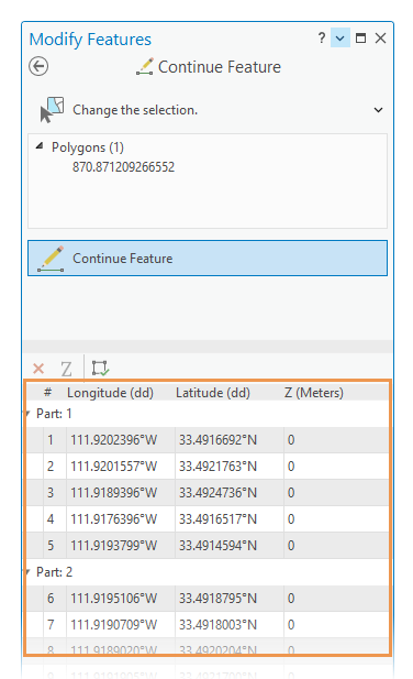
The Edit Vertices  and Continue Feature tools allow you to edit the vertices of a multipart polygon feature in a geometry properties table and delete a component part representing a hole. These tools are available in the Modify Features pane.
When you fill a hole in a polygon feature, consider the following:
- Feature attribute values are preserved when a part is deleted in the geometry properties table.
- To remove a hole based on area calculations, use the Eliminate Polygon Part geoprocessing tool.
- To draw a new feature instead, use the Trace tool and copy the feature attributes with the transfer attribute values tool.
Dive-in:
Other ways to fill a hole include the following advanced methods:
- Draw and finish an adjoining feature across the void with the Auto Complete Polygon tool. Use the Merge tool to merge the features, and preserve the feature containing the attributes you want to keep.
- If your polygon feature data participates in a geodatabase topology, add the rule Must Not Have Gaps to the feature class and validate the topology in the map with Error Inspector
 . After the futures are validated, use the Create Feature tool
  on the Fix tab and create new polygon features.
 - To create a feature from a part representing a hole, copy and paste the multipart feature using the clipboard commands. Edit the new feature and delete the outer boundary.
Delete a part representing a hole
To delete a part presenting a hole, complete the following steps:
- Add your data and configure settings for editing.
Confirm that the feature layer you are editing is editable, the coordinate system assigned to the active map is suitable for the type of edits you're performing, and snapping is configured to help you work efficiently and accurately.
- On the ribbon, click the Edit tab. In the Features group, click Modify
 .
. The Modify Features pane appears.
- Click Continue Feature
 or Edit Vertices
  .
.To find the tool, expand Reshape, or type Cont or Vertices, respectively, in the Search text box.
- Click the Change the selection tool
 in the tool pane and select a polyline or polygon feature.
If you select more than one feature, reselect the feature. Alternatively, click the feature in the pane selection view to flash it in the map, right-click, and click Only Select This
 .
. Note:
If you are using Edit Vertices
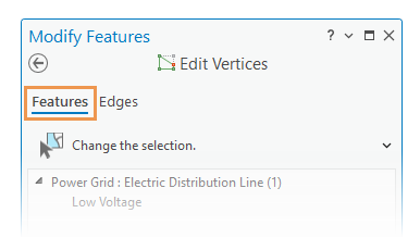
 and Map Topology is enabled, click the Features tab.
The Features and Edges tabs are not required to complete this workflow. These tabs are available only when map topology or a geodatabase topology is enabled so that you can switch between editing feature vertices and topological edges and nodes.

The selected feature appears highlighted in the map with vertex handles. By default, project settings symbolize the first vertex in green and the last vertex in red.
- Right-click the part header for the hole in the geometry properties table, and click Delete Part
 .
.Tip:
Right-click the part header, and click Pan to part if the feature is not in the current view.

- Click Finish
 on the construction toolbar, or press the F2 key.
Create a feature and copy attributes
To create a feature and copy attributes to the new feature, complete the following steps:
- Add your data and configure settings for editing.
Confirm that the feature layer you are editing is editable, the coordinate system assigned to the active map is suitable for the type of edits you're performing, and snapping is configured to help you work efficiently and accurately.
- On the ribbon, click the Edit tab. In the Features group, click Create
 .
. - In the Create Features pane, click a polygon feature template for the same layer.
To find a feature template containing a specific word or phrase, click the Search box
 and enter your search criteria. Search is not case sensitive.
 - Click the Trace tool
 on the template tool palette.
Alternatively, click the Polygon tool
 on the tool palette, and click the Trace tool
  on the construction toolbar.
 Tip:
Press the O key and confirm that the optional trace setting Trace with an offset is not checked.
- Trace the boundary of the source feature.
To avoid inserting unnecessary vertices into the new geometry, complete the following steps:
- Snap to a vertex and move the pointer along the feature boundary. A rubber band line shows your progress.
- Snap to the last vertex preceding the first vertex you snapped.
- Click Finish
 on the construction toolbar, or press the F2 key.
The new polygon feature contains the default attribute values defined by the feature template or source geodatabase.
- Copy the attributes on the source feature to the new target feature.
- Click the Transfer Attributes tool
 in the Modify Features pane.
 To find the tool, expand Attributes, or type Attr in the Search text box.
- Click the source feature containing the hole.
- Press the Shift key and click the new traced target feature.
The target feature contains the same attribute values as the source feature.
- Click the Transfer Attributes tool