The Union tool calculates the tool geometric union of any number of feature classes and feature layers.
License:
The ArcGIS Desktop Basic and Desktop Standard licenses limit the number of input feature classes or layers to two.
All input feature classes or feature layers must be polygons.
The output feature class will contain polygons representing the geometric union of all the inputs as well as all the fields from all the input feature classes. See below for examples of how attribute values are assigned to the output features.
The Union tool does the following:
- Determines the spatial reference for processing. This will also be the output spatial reference. For details on how this is done, see Spatial reference and geoprocessing. All the input feature classes are projected into this spatial reference.
- Cracks and clusters the features. Cracking inserts vertices at the intersection of feature edges; clustering snaps together vertices that are within the x,y tolerance.
- Finds geometric relationships (overlaps) between features from all feature classes.
- Writes these overlaps to the output.
When multiple feature classes or layers are specified in the list of input features, the order of the entries in the list does not affect the output feature type, but the spatial reference of the top entry on the tool dialog box (the first entry in scripting) in the list will be used during processing and set to the output.
To explicitly control the output spatial reference (coordinate system and domains), override the default spatial reference properties using the appropriate geoprocessing environments.
Tip:
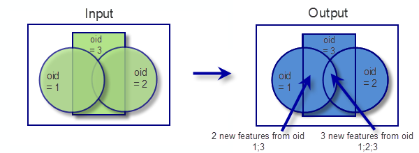
The Union tool can run with a single input feature class or layer. With a single input, instead of finding overlap between the features from the different feature classes or layers, the tool will find the overlap between features within the single input. The areas where features overlap will be separated into new features with all the attribute information of the input feature. The area of overlap will always generate two identical overlapping features, one for each feature that participates in that overlap.
The graphic below illustrates the result of the union of overlapping features within a feature class. The area of overlap is duplicated to maintain all the attributes and areas. To re-create the overlapping features, use the Dissolve tool on the output, and dissolve by all fields except the FID field.

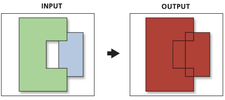
The graphic below illustrates running the Union tool with the Gaps Allowed parameter unchecked. A polygon feature is created in what would otherwise be an empty space. These features can be identified by doing an attribute query of the input feature's FID fields that equal -1. All other attribute values for the gap features will have their values set to empty strings or 0.
