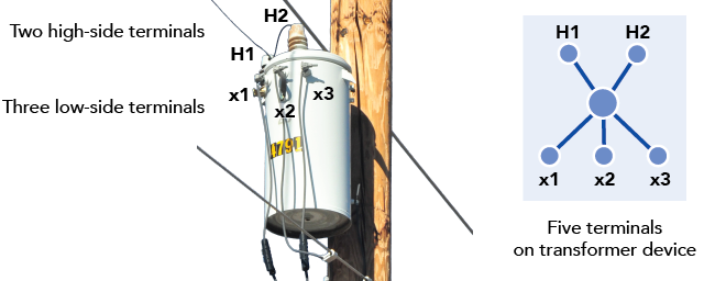
With a utility network, you can model features to a high degree of realism with terminals on devices and junction objects. Features in the field have defined locations or connection points from which resources, such as electricity and water, flow in and out. A utility network allows you to optionally model these ports with terminals.
Every device in the field can be physically connected to one or more lines. When these connection points are explicitly modeled in the GIS we refer to them as terminals. The utility network can model multiple, distinct connections to a device or junction object using terminals. These may be in the form of bushings on a transformer, the inlet/outlet of a regulator, or the ports on a manifold, for example. Terminals are an optional configuration for devices and junction objects and are only required for a feature to act as a subnetwork controller.

For example, an electric distribution transformer (shown above) has five bushings (connection points), two on the high side named H1 and H2 and three on the low side named x1, x2, and x3. You can model this transformer in one of two ways: with a simple two-terminal configuration or a detailed five-terminal configuration. The five-terminal configuration corresponds more closely to the bushings on the physical transformer and is preferable if you want to achieve a high-fidelity representation.
When to use terminals
Terminals are only required on devices and junction objects that can act as subnetwork controllers. For example, in an electrical system, a subnetwork typically begins at the line side terminal of a circuit breaker in a substation. Some analytical models, such as electric voltage drop analysis or hydraulic models can benefit from a model that includes devices with terminals because this enables unambiguous modeling of both the external and internal connectivity of the device.
Not all features require the definition of terminals. If a feature can be connected to multiple features and each connection is equal and interchangeable, such as the two sides of a switch or valve, terminals do not need to be defined.
The situations where you should define terminals are as follows:
- Features that will serve as a subnetwork controller
- Features with three or more physical connection points that you need to model
- Features with two connection points that are distinctly different, such as a high-side and low-side port on a transformer device
- Features with connections that only allow flow in one direction, such as check valves in a water system or network protectors in an electric system
Connectivity
Terminals are not features and do not appear on the map. They exist as logical connection locations on a device or junction object that allow you to control how other features can connect, and the valid paths through which a network commodity can travel.
You can use the Modify Terminal Connections pane or snap chip to set a terminal connection between a line feature and a terminal on a device feature. The Modify Terminal Connections pane is also used to list existing terminal connections for a selected line feature, change the terminal to which the line is connected, or disconnect a line from a device terminal. This updates the values for the From device terminal and To device terminal attributes on the Line classes. When working with junction and edge objects, use the Modify Associations pane to set or modify a terminal connection between a device feature or edge object and the terminal on a junction object through a connectivity association. Terminal connectivity is enforced using network rules.
Note:
The From device terminal and To device terminal attributes refer to the device at the first vertex and last vertex of the line respectively and are not related to the direction in which resources flow in the network. For example, in an electric system, you connect the high-side terminal of a distribution transformer to a line with medium voltage, and the low-side terminal to a line with low voltage. If the low voltage line was digitized from the service to the transformer, the To device terminal on the line would correspond with the low-side terminal on the transformer.
While possible, it is not recommended to edit these attribute fields on the line feature directly because the attribute editor does not have the same intelligent editing behaviors available using other methods.
To learn more about terminal connectivity, see Modify terminal connections.
Terminal configurations
The terminals available on a feature are determined by the terminal configuration assigned to the feature's asset type. Each utility network can be configured to support many terminal configurations. Terminal configurations can only be assigned to specific asset types in the Device feature class or JunctionObject table.
A terminal configuration has a directionality setting that dictates whether flow through the device is constrained to be directional. It has a set number of terminals, each with a name. Terminal configurations with three or more terminals have valid paths defined to constrain how the resources flow through the paths between pairs of terminals. To learn more, see Terminal management.