The Control Measure Line symbol effect creates various dynamic geometries based on the order of vertices on a line feature. The rules in this symbol effect can be used to author parts of symbols to support ordered anchor points as defined in the Joint Military Symbology and NATO Joint Military Symbology specifications.
The following table outlines the rule options of the Control Measure Line symbol effect. The first column provides construction guides and the last column shows an example of the rule used to build a symbol from the specification.
| Rule and construction guide | Description | Example |
|---|---|---|
Full Geometry | Draws identical to the feature geometry. This is the default rule. |  |
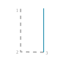
Perpendicular From First Segment | Creates a dynamic line from vertex 3 to the first segment midpoint. |  |
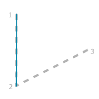
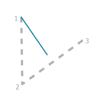
Reversed First Segment | Creates a dynamic line between vertex 2 and vertex 1. The line begins at vertex 2. | 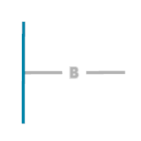 |
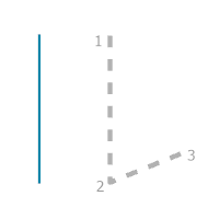
Perpendicular To Second Segment | Creates a dynamic line from the midpoint of the second segment to the vertex 1. |  |
Second Segment With Ticks | Creates a dynamic line between vertex 2 and vertex 3 with ticks on the ends. |  |
Double Perpendicular | Creates dynamic lines parallel to vertex 3 and the midpoint of the first segment. The separation width of the parallel lines is determined by the length of the first segment. | 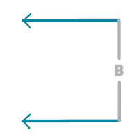 |
Opposite To First Segment | Creates dynamic lines perpendicular to vertex 3 and the midpoint of the first segment with the length determined by the first segment. |  |
Triple Perpendicular | Creates three dynamic lines parallel to vertex 3 and the midpoint of the first segment. The top and bottom lines stop at 80% of the first segment. |  |
Half Circle First Segment | Creates a dynamic half circle centered on the midpoint of the first segment. The orientation of the half circle is opposite vertex 3. | 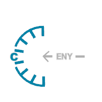 |
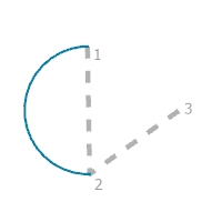
Half Circle Second Segment | Creates a dynamic half circle ending on vertex 2 opposite vertex 1. The diameter of the half circle is defined by vertex 3. |  |
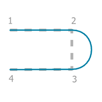
Half Circle Extended | Creates a dynamic U-shaped line with a curve between vertex 2 and vertex 3. Control points are placed on vertex 1 and vertex 3 to allow the placement of markers. | 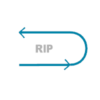 |
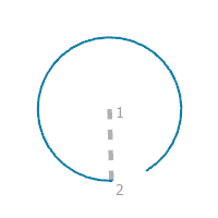
Open Circle | Creates a dynamic 330° circular arc centered on vertex 1, starting at vertex 2. | 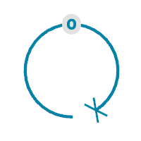 |
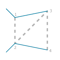
Coverage Edges With Ticks | Creates dynamic lines between vertex 1 to vertex 3 and vertex 2 to vertex 4. Angled ticks are placed at the end of the lines at vertex 1 and vertex 2. |  |
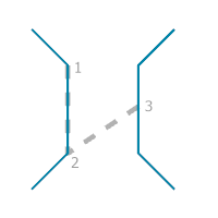
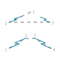
Gap Extent With Double Ticks | Creates two dynamic lines with angled ticks on the ends. Lines are created along the first and third segments. | 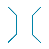 |
Gap Extent Midline | Creates a dynamic line centered between the first and third segments. |  |
Chevron | Creates a dynamic line in the shape of a chevron with the apex at vertex 1 and the ends at vertex 2 and vertex 3. | 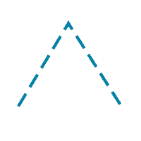 |
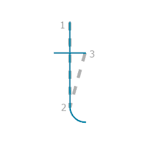
Perpendicular With Arc | Creates a dynamic line between vertex 1 and vertex 2 with an arc off vertex 2. A cross line is perpendicular to vertex 3. | 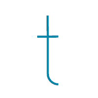 |
Closed Half Circle | Creates a dynamic semicircle with corners at vertex 1 and vertex 2. |  |
Triple Parallel Extended | Creates three dynamic parallel lines of varying length connected to a baseline. The baseline is defined by the first segment. Vertex 3 is the end of the longest line. |  |
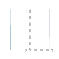
Parallel With Ticks | Creates a dynamic line with angled ticks on the ends between vertex 1 and vertex 2. A mirrored parallel line is placed at the width defined by vertex 3. | 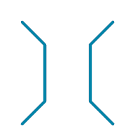 |
Parallel | Creates a dynamic line between vertex 1 and vertex 2 and a parallel line with a separation width defined by vertex 3. |  |
Perpendicular To First Segment | Creates a dynamic line perpendicular to the midpoint of the first segment. The length is 50% longer than the second segment. | 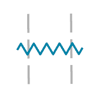 |
Parallel Offset | Creates dynamic parallel lines offset from the first segment. The offset is determined by vertex 3. | 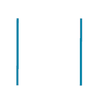 |
Offset Opposite | Creates a dynamic single line offset from the first segment. The offset is on the opposite side of vertex 3, defined by vertex 3. |  |
Offset Same | Creates a dynamic single line offset from the first segment. The offset is on the same side as vertex 3, defined by vertex 3. |  |
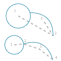
Circle With Arc | Creates a dynamic circle centered on vertex 1 with a 90° arc attached. Vertex 3 determines the side of the 90° arc. If there are three vertices, vertex 2 determines the length of the arc. If there are four vertices, vertex 2 determines the radius of the circle and vertex 4 determines the length of the arc. |  |
Double Jog | Creates two dynamic lines with jogs and a gap at their centers. If there are three vertices, the gap is centered on vertex 1. If there are four vertices, the gap is defined by the second segment. |  |
Perpendicular Offset | Creates a dynamic line perpendicular from the midpoint of the second segment. The end point is offset from the second segment. Vertex 1 determines the length of the line. | 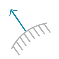 |
Line Excluding Last Segment | Creates a dynamic line along the geometry between vertex 1 and the second to last vertex. | 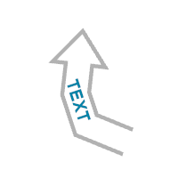 |
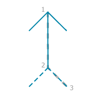
Multivertex Arrow | Creates a dynamic line forming an arrow. Vertex 1 determines the tip and the last vertex determines the width and back of the arrowhead. |  |
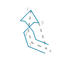
Crossed Arrow | Creates a dynamic line forming a crossed arrow. Vertex 1 determines the tip and the last vertex sets the width and back of the arrowhead. The arrow is crossed at the midpoint between vertex 1 and vertex 2. | 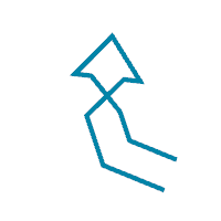 |
Chevron Arrow | Creates a dynamic line forming a chevron arrow centered on vertex 1. |  |
Chevron Arrow Offset | Creates a dynamic line forming a chevron arrow centered on vertex 1 and offset toward vertex 2. |  |
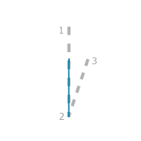
Partial First Segment | Creates a dynamic line along the first segment, starting at vertex 2 and extending in the direction and length of vertex 3. | 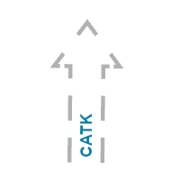 |
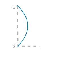
Arch | Creates a dynamic three-point arched line between vertex 1 and vertex 2. Vertex 3 determines the depth of the arch. |  |
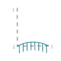
Curved Parallel Ticks | Creates a dynamic curved line with ticks. The curve begins on vertex 2 and ends on vertex 3. Ticks are added on the opposite side of vertex 1. | 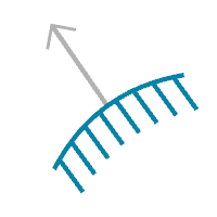 |
Arc 90 Degrees | Creates a dynamic 90° arc with ends at vertex 1 and vertex 2. Vertex 3 determines the side of the curve. | 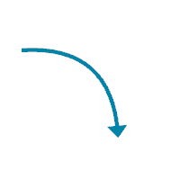 |
Tip With Perpendicular And Ticks | Creates a dynamic line perpendicular to segment 1, centered on vertex 1 and offset toward vertex 2 with ticks. The tip of segment 1 connects to the perpendicular line from vertex 1. The length of the perpendicular line is determined by the last vertex. | 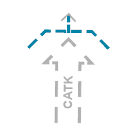 |
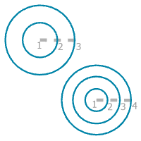
Concentric Circles | Creates two or three concentric circles centered on vertex 1. Circle radius is based on vertex location. |  |
Double Jog Arrow | Creates two dynamic lines with jogs centered on vertex 1. | 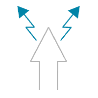 |
Linked Chevrons | Creates a dynamic line between vertex 1 and 2 connecting two chevrons. Vertex 3 defines the width of the chevrons. |  |
Segment Then Half Circle | Creates a dynamic line with a straight segment followed by a half circle. The diameter of the circle is determined by the length of the second segment. Vertex 4 determines the side of the half circle. | 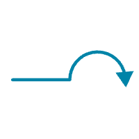 |
Line With Straight Ticks | Creates a dynamic line with vertex 1 in the middle. Vertex 2 and 3 define the length of the ticks and the line. | 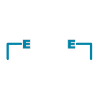 |
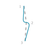
Double Curve | Creates a dynamic line with alternating curves at vertex 2. |  |
Parallel With Ticks By Width | Creates a dynamic line with angled ticks on the ends between vertex 2 and vertex 3. A mirrored parallel line is placed at the width defined by vertex 2. |  |
Enclosing Rounded Rectangle | Creates an enclosing rectangle around the line with rounded corners. |  |


