Available with Location Referencing license.
You can update route geometry based on aerial imagery, as-built drawings, or input from field data collectors without changing measures by making direct modifications to the centerline. This process is known as cartographic realignment. ArcGIS Roads and Highways allows you to change the shape of centerlines and preserve the calibration of the underlying routes as they existed before the cartographic realignment.
Note:
The centerline feature class must be visible in the Contents pane to apply cartographic realignment.
Tip:
Cartographic realignment uses the LRS Network's Update route measures in cartographic realignment property. This property is disabled by default. It can be enabled for routes in the LRS Network using the Update route measures in cartographic realignment parameter of the Modify Network Calibration Rules tool.
Learn more about updating route measures and events after cartographic realignment
To apply cartographic realignment, complete the following steps:
- Add the
centerline and network feature class to a map.
Alternatively, open a map in which the centerline and network feature class are present.
Note:
- In the data model, only one centerline is expected at any given location. Ensure that the centerlines you're using for your edit do not overlap other centerlines in the LRS.
- Branch versioned networks, including any network configured with a user-generated route ID, must be edited through a feature service.
- Zoom in to the location of the alignment change.
Note:
The centerline feature for cartographic realignment of the route must exist in the centerline feature class before the realignment.
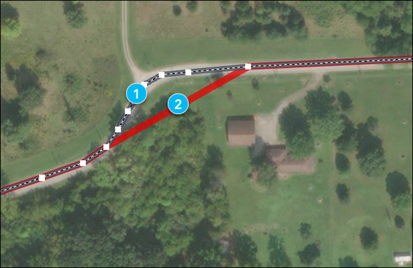
The numbers in the image above correspond to the numbers in the following table:
Component Description 
Correct alignment

Incorrect alignment
- In the Contents pane, on the List By Selection tab
 , in the Selection list, uncheck the network layer.
 - In the Contents pane, on the List By Selection tab
 , in the Selection list, check the centerline layer.
 - Select the centerline feature in the map for editing.
- Edit the centerline's vertices as necessary.
You can edit feature vertices and modify centerline segments using the Edit Vertices tool.
The numbers in the image above correspond to the numbers in the following table:
Component Description 
Updated centerline

Original centerline
- After editing the vertices to match the proposed alignment of the route, right-click anywhere on the map, and click Finish
 .
.The route is cartographically realigned.
Vertices on the route are impacted by the cartographic realignment based on the configured cartographic realignment option.

Note:
- After the centerlines are updated, the route shapes in all networks are also updated. However, the event shapes for events and locations of the managed intersections are not updated until you run the Apply Event Behaviors and Generate Intersections geoprocessing tools.
Learn more about scenarios for generating and updating intersections
- It is also important to note that when the centerlines are edited, all routes in all networks, across all times, are modified accordingly.
- If conflict prevention is enabled, locks are acquired on all routes associated with the centerline being edited.
Note:
If a message regarding acquiring locks or reconciling appears, conflict prevention is enabled.
After a route is selected, the tool will attempt to release the route lock if the route lock is acquired by the active user in a different version and its releasable status value is Yes.
- After the centerlines are updated, the route shapes in all networks are also updated. However, the event shapes for events and locations of the managed intersections are not updated until you run the Apply Event Behaviors and Generate Intersections geoprocessing tools.
Complex route cartographic realignment scenarios
Scenarios for complex route cartographic realignment on loop and lollipop routes when Update route measures in cartographic realignment is disabled are described below.
Cartographic realignment on a loop
In the following example, an undershoot is fixed on a loop route that has a start measure of 0 and an end measure of 4 before cartographic realignment:
After cartographic realignment, the undershoot on the loop is fixed and two intermediate calibration points are added at measures 1.33 and 2.67.
Note:
If the Update route measures in cartographic realignment property is disabled, then existing intermediate calibration points will have updated measures to account for the shape change. If this property is enabled, only calibration points upstream of the cartographic realignment will have their measures changed.
This means, in the example above, the location of the intermediate calibration points stays the same, but their measures can change.
Cartographic realignment on a lollipop
In the following example, an undershoot is fixed on a lollipop route that has a start measure of 0 and an end measure of 5 before cartographic realignment:
After cartographic realignment when Update route measures in cartographic realignment is disabled, the undershoot on the lollipop is fixed and two intermediate calibration points are added at measures 2.46 and 3.86.
In the following example, an overshoot is fixed on a lollipop route that has a start measure of 0 and an end measure of 5 before cartographic realignment:
After cartographic realignment when Update route measures in cartographic realignment is disabled, the overshoot on the lollipop is fixed.