The Pairwise Intersect tool calculates the intersection between the features in two feature layers or feature classes using a pairwise comparison technique. The tool outputs the features, or portion of features, that are common to both inputs.
Intersect and Pairwise Intersect tool comparison
With the Pairwise Intersect tool, one feature from the first input is intersected with each individual feature in the second input. This is fundamentally different than how the Intersect tool works. With the Intersect tool, all features are intersected regardless of which input the feature belongs to.
The Intersect tool does the following:
- Intersect multiple feature layers or feature classes
- Finds the intersection of all input features, regardless of which input they belong to, creating a topological fabric representing the geometric intersection of all features
The Pairwise Intersect tool does the following:
- Only accepts two feature layers or feature classes as input
- Takes features from the first input and intersects them with each feature in the second input, one at a time, creating new features representing their intersection
Intersect tool
All intersections among all features are calculated, regardless of what input they belong to. Because all intersections are calculated, the output may contain many more features than the count of all the input features combined. For example, two inputs with a combined tens of thousands of features, could result in an output of hundreds of millions of features due to the complex overlaps that exist between all the features.
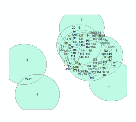
For example, two feature layers are shown below; the first contains 10 features, and the second contains a single feature.

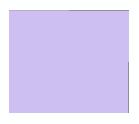
The image below shows the result of the Intersect tool with the two inputs. Intersections for all features are calculated, regardless of which input. This can result in many more features than found in the inputs. In this case, there are more features in the output (167) than there are in both inputs (11).
Pairwise Intersect tool
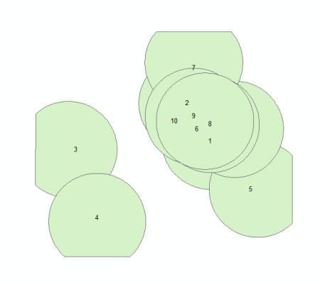
The Pairwise Intersect tool creates simpler output. The tool does not calculate the intersection of features within the same input; intersections are only calculated between features in the different inputs.
The image below shows the result of the Pairwise Intersect tool with the two inputs. The output includes only 10 features.
Polygon inputs and point output
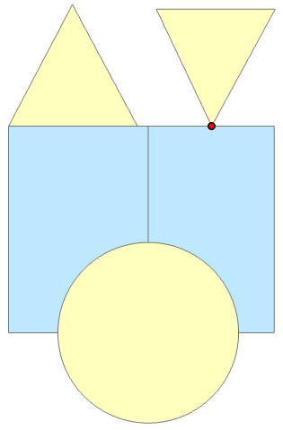
The images below show the result of two input polygon feature layers when the Output Type parameter is set to Point.
The Intersect tool creates point features where a polygon from either input has a vertex that intersects the boundary of a polygon from the other input where they touch at a point or where their borders cross.

The Pairwise Intersect tool creates point features where a polygon from one of the inputs has a vertex that touches the boundary of a polygon from the other input.
Polygon inputs completely overlap with line and point output
The Intersect and Pairwise Intersect tools return different results with input polygon features that completely overlap when the Output Type parameter is set to Point or Line.
The image below shows the result of intersecting two polygon feature layers using the Intersect tool with the Output Type parameter first set to the Point option (purple output point feature) and second to the Line option (red output line feature). The polygons from the two inputs completely overlap one another with one set of polygons also intersecting on a boundary and one set of polygons intersecting at a single point.
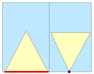
Using the Output Type parameter's Point option, the Intersect tool will output the purple point feature (purple) due to the yellow polygon feature touching the boundary of the blue polygon boundary. This touches intersect relationship will result in an output point regardless of the polygons completely overlapping.
Using the Output Type parameter's Line option, the Intersect tool will output the red line feature due to the yellow polygon feature sharing a boundary with the blue polygon. This shared boundary intersect relationship will result in an output line feature regardless of the polygons completely overlapping.
For both of these cases, the Pairwise Intersect tool will return an empty output. Polygons that completely overlap will result in only the area overlap relationship being valid, and no lower order intersection relationships are considered valid.
Differences during processing
The Pairwise Intersect and Intersect tools have the following differences during processing.
Performance
The Pairwise Intersect tool may provide substantial performance gains over the Intersect tool when intersecting massively overlapping features. When the amount of overlap is minor, there may be no performance gains.
Note:
The output can be very different between the two tools. Experiment with small subsets of data in order to analyze the output and determine which tool is most appropriate.
The Intersect tool identifies unique incidents of overlap between all features in the inputs. Considering the complexity of this type of operation, the Intersect tool is efficient and scales well. If you need to find unique incidents of overlap between all the features in your inputs, use the Intersect tool.
X,y resolution
X,y resolution is the numeric precision used to store x,y-coordinate values. All calculations in the Pairwise tools are performed using floating point. The coordinates are stored in the floating point format with double precision (also known as doubles). This is different from tools like the Intersect tool (most non-Pairwise tools) that internally use integers for the coordinates, storing values on the integer grid.
Difference in how the X,y tolerance is applied
X,y tolerance defines the minimum distance between coordinates when processing geometries in operations such as simplify and topological operations. The term cracking and clustering is used to describe the process of splitting the intersecting segments and snapping the points. The cracking process is when segments are split at the points of intersection with other segments or points. The clustering process is when the close vertices are snapped together, because they are considered equal. For more information, see Understanding Geometric Processing.
Note that point means either a stand-alone point, in a multipoint for example, or a vertex of a segment.
Cracking and clustering using non-Pairwise tools
During the Intersect tool cracking process, a point is assumed to be on the segment if the closest distance from the point to the segment interior is less than or equal to sqrt(2) * tolerance. In that case, the segment will be split, and the new endpoints will be snapped with the point.
When performing the clustering process using the Intersect tool, two points will be snapped together when the distance between them is less than or equal to 2 * sqrt(2) * tolerance. The clustering algorithm is iterative, so in some cases, coordinate locations may shift more than this distance.
When two points are snapped together or when a point is snapped with a segment, the segments move a little. New intersection events may occur, because a segment that has moved may become closer than the sqrt(2) * tolerance from another vertex.
The coordinates of the snapped vertices or intersection points of the segments will be stored in the integer grid. Therefore, they are calculated up to the resolution accuracy, and the rounding to the integer grid causes new vertices to move a little. Because of that, the cracking and clustering process is repeated until no new cracking and clustering events occur.
Cracking and clustering in Pairwise tools
The Pairwise tools use floating point values for all calculations. The result of processing has to be considered clean (not requiring repair) by non-Pairwise tools. That is, when a set of geometries is processed by a non-Pairwise tool, the result will be such that all non-Pairwise tools will not find any new segment intersections or points that should have been cracked or clustered but were not.
Simplify and topological operators
During the Pairwise cracking process, a point is assumed to be on the segment if the closest distance from the point to the segment interior is less than or equal to 1.01 * sqrt(2) * (tolerance + 2 * resolution).
When Pairwise tools perform clustering, two points are snapped together when the distance between them is less or equal to 1.01 * sqrt(2) * (2 * tolerance + 2 * resolution). The clustering algorithm is iterative, so in some cases, coordinate locations may shift more than this distance.
A value of 1.01 is used to increase the original value by 1 percent for stability.
Which tool to use
Choose a tool based on performance needs and the type of output required for your analysis. If the Intersect tool completes in a reasonable amount of time and creates output suitable for your analysis, continue to use it.
However, if the Intersect tool does any of the following, consider using the Pairwise Intersect tool, if the output it creates is suitable for your analysis.
- The tool takes a long time to run.
- The tool fails due to lack of resources.
- The tool creates a multitude number of output features compared to the number of input features.