| Label | Explanation | Data Type |
Input Features | The features that will be clipped. | Feature Layer |
Clip Features | The features that will be used to clip the input features. | Feature Layer |
Output Feature Class | The feature class that will be created. | Feature Class |
XY Tolerance (Optional) | The minimum distance separating all feature coordinates (nodes and vertices) as well as the distance a coordinate can move in x or y (or both). Caution:Changing this parameter's value may cause failure or unexpected results. It is recommended that you do not modify this parameter. It has been removed from view on the tool dialog box. By default, the input feature class's spatial reference x,y tolerance property is used. | Linear Unit |
Use maximum precision (Optional) | Specifies the level of precision that will be used when processing the data.
| Boolean |
Summary
Extracts input features that overlay the clip features.
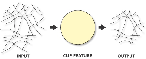
Use this tool to cut out a piece of one feature class using one or more of the features in another feature class. This is particularly useful for creating a new feature class—also referred to as a study area or area of interest (AOI)—that contains a geographic subset of the features in another, larger feature class.
Clip operations can also be performed with the Clip tool.
Illustration

Usage
The Clip Features parameter values can be points, lines, or polygons, depending on the geometry type of the Input Features parameter value.
- When the Input Features parameter value is polygon, the Clip Features parameter value must also be polygon.
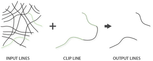
- When the Input Features parameter value is line, the Clip Features parameter value can be line or polygon. When clipping line features with line features, only the coincident lines or line segments will be written to the output, as shown in the image below.
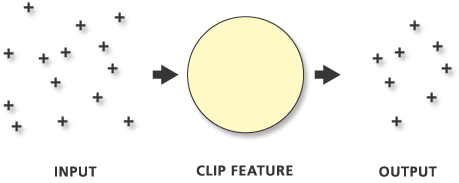
- When the Input Features parameter value is point, the Clip Features parameter value can be point, line, or polygon. When clipping point features with point features, only the coincident points will be written to the output, as shown in the image below. When clipping point features with line features, only the points that are coincident with the line features will be written to the output.
The Output Feature Class parameter will contain all the attributes of the Input Features parameter.
Line features clipped by polygon features:

Point features clipped by polygon features:

Line features clipped with line features:

Point features clipped with point features:

When the Use maximum precision parameter is checked, the tool will apply a level of accuracy that is greater than the default for the input spatial reference when processing the data.
Precision is a combination of the x,y resolution and x,y tolerance that is used during processing. By default, the tool will use these properties from the first Input Features parameter value's spatial reference.
When the Use maximum precision parameter is checked, the maximum possible precision value will be used for point output. The tool uses the maximum accuracy that is available to the tool, which depends on the absolute value of the geometry coordinates and the accuracy of the hardware floating point. A rough estimate of the maximum tolerance that will be used is 0.002 millimeters as compared to 1 millimeter for the default.
When the output is written, the resolution of the spatial reference will be applied, so the vertices may shift slightly.
When the input data contains nonlinear segments (curves), for best results, enable the Maintain Curve Segments environment and set the Curve Processing Method environment to Exact.
This tool honors the Parallel Processing Factor environment. If the environment is not set (the default) or is set to 100, full parallel processing will be enabled and the tool will attempt to distribute the work to all the logical cores on the machine. If the environment is set to 0, parallel processing will not be enabled. If a factor between 1 and 99 is specified, the tool will identify the percentage of logical cores to use by applying the formula (Parallel Processing Factor / 100 * Logical Cores) rounded up to the nearest integer. If the result of this formula is 0 or 1, parallel processing will not be enabled.
Parameters
arcpy.analysis.PairwiseClip(in_features, clip_features, out_feature_class, {cluster_tolerance}, {precision})| Name | Explanation | Data Type |
in_features | The features that will be clipped. | Feature Layer |
clip_features | The features that will be used to clip the input features. | Feature Layer |
out_feature_class | The feature class that will be created. | Feature Class |
cluster_tolerance (Optional) | The minimum distance separating all feature coordinates (nodes and vertices) as well as the distance a coordinate can move in x or y (or both). Caution:Changing this parameter's value may cause failure or unexpected results. It is recommended that you do not modify this parameter. It has been removed from view on the tool dialog box. By default, the input feature class's spatial reference x,y tolerance property is used. | Linear Unit |
precision (Optional) | Specifies the level of precision that will be used when processing the data.
| Boolean |
Code sample
The following Python window script demonstrates how to use the PairwiseClip function in immediate mode.
import arcpy
arcpy.env.workspace = "C:/data"
arcpy.analysis.PairwiseClip("majorrds.shp", "study_quads.shp",
"C:/output/studyarea.shp")The following Python script demonstrates how to use the PairwiseClip function in a stand-alone script.
# Description: Clip major roads that fall within the study area.

# Import system modules
import arcpy

# Set workspace
arcpy.env.workspace = "C:/data"

# Set local variables
in_features = "majorrds.shp"
clip_features = "study_quads.shp"
out_feature_class = "C:/output/studyarea.shp"

# Run Pairwise Clip
arcpy.analysis.PairwiseClip(in_features, clip_features, out_feature_class)
Environments
Licensing information
- Basic: Yes
- Standard: Yes
- Advanced: Yes