Overlap classification is a common processing step for aerial lidar. The goal is to achieve a relatively even point distribution that allows subsequent geometric and statistical processes to be run more efficiently and reliably.
With aerial lidar, collections are usually gathered by a plane flying in successive, parallel paths. Along each path, a swath of data is collected. Neighboring swaths overlap to some degree. This is done purposefully to ensure complete coverage, so there are no gaps, or holidays, in the data.
Within areas of overlap, the point density is twice as high as in areas where there is no overlap.
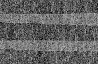
The calibration of data between flight paths is not always perfect. This can lead to slight height offsets between flight paths. The offset becomes most apparent in areas of overlap toward the edges of the flight paths. Even with excellent calibration, the higher density of points in overlap areas effectively results in more apparent noise. This is because points are closer together in x,y but height variations between neighboring points remain constant (in other words, the same vertical displacement, due to limits in vertical accuracy, over shorter distance equals greater slope). A surface formed in areas of overlap will have larger average slopes than in areas of no overlap.
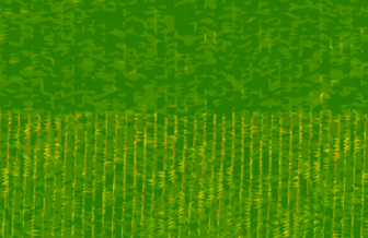
To make the point density more consistent, while minimizing the impact of noise and calibration issues, you can exclude some of the points from the area of overlap. This is accomplished with an overlap classification. This classifies, or flags, a subset of points in overlap areas. Overlap points can then be excluded from subsequent classification and analytic steps. For example, the Classify LAS Ground and Classify LAS Building geoprocessing tools automatically exclude use of overlap points.
Prerequisites
The following are necessary before classifying overlap:
- A point source ID is used to identify which flight path a point belongs to. This information should be assigned for each point and is usually done by the data provider.
- Data from different flight paths should be merged and tiled into one set of contiguous, nonoverlapping tiles. The Tile LAS geoprocessing tool can be used for this.
- The data must be in a projected coordinate system. If the LAS data is in a geographic coordinate system, it must be reprojected into a projected coordinate system. The Extract LAS geoprocessing tool can be used to project the data.
Review the LAS data's use of point source ID
When using the Classify LAS Overlap geoprocessing tool, it is assumed that the point source ID of each point is set to the number of the flight path where it originated. This flight path assignment is a common practice performed by most data providers. However, the LAS specification doesn’t make it clear this is a requirement, and the wording is open to interpretation.
To display the points symbolized by the source ID, complete the steps below.
- Add the LAS dataset layer to a 2D map or 3D local scene.
- Open the Symbology pane for the LAS dataset layer.
- On the Points tab, next to the checked Draw using check box, choose Point source ID from the drop-down list.
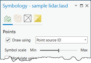
The upper portion of the Symbology pane for a LAS dataset is shown with points selected to be displayed by a point source ID.
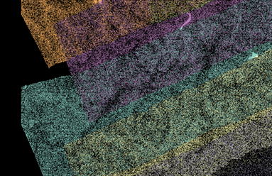
When the point source ID is set to the flight path number, you would expect the points to display in the same color for each swath, with swaths generally oriented parallel to one another with at least some degree of overlap between them.
Classify LAS Overlap tool
The Classify LAS Overlap geoprocessing tool partitions the points into square bins. It then examines the scan angle rank of all points in each bin. The scan angle rank is the scan angle of the point relative to nadir, directly below the plane and the scanner. Values can range from -90 to 90 degrees. The point source ID (flight path ID) for the point whose scan angle rank is closest or equal to 0.0 is identified as the one that will be used for classification and analysis. The concept is that points closer to nadir are more accurate than points toward the edge of the swath. Points in the bin that do not belong to the chosen flight path are classified, or flagged, as overlap points. For LAS version 1.4 files, which typically use point formats 6-8, an overlap flag bit is set to achieve this. For other LAS file versions and point formats, the overlap class code of 12 is used.
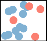
The image above shows a sample bin, a couple meters on a side, of lidar points. The blue points belong to one flight path; the orange points belong to another. The minimum absolute scan angle for the blue points is 5. The minimum absolute scan angle for the orange points is 17. Blue, being closer to nadir, or 0, is considered more accurate. Consequently, the orange points will be flagged as overlap.
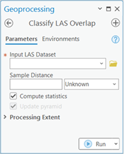
The Sample Distance parameter represents the size of bins used to partition the points. Bins are 2D squares, and the sample distance is the length of the side of the bin.
The sample distance you provide should be at least several times the nominal point spacing. It can be even greater, considering its purpose is to determine which flight path’s data is to be used for a given area. Up to several meters is reasonable. Once overlap points are classified, they can be excluded from display and subsequent analysis by filtering them out. Right-click the LAS dataset layer in the Contents pane and choose Properties. On the LAS Filter tab, under Classification Flags, uncheck Overlap.
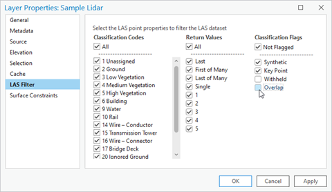
Point filter settings for turning on and off overlap points are available from the LAS dataset properties. The image above is for LAS version 1.4 files in which the overlap class flag is used instead of the overlap class code.
When you visualize LAS data using the point source ID after filtering out the classified points, you will see a clean boundary between the flight lines, as shown in the images below. The first image shows points with overlap, and the second image shows points with no overlap.
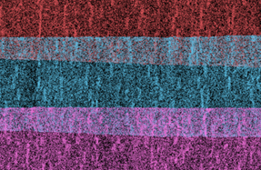
Identifying overlap, to exclude it, will yield a more consistent point density and can improve results from subsequent operations such as ground classification, building classification, and DEM production.