Available with Standard or Advanced license.
Available for an ArcGIS organization with the ArcGIS Reality license.
If you have an existing mosaic dataset managing drone, digital aerial, or satellite imagery data, you can improve the data accuracy and generate Reality mapping products. This is done by creating a Reality Mapping workspace from an existing mosaic dataset.
The following are examples of use cases for this workflow:
- You have a mosaic dataset managing drone or digital aerial data that has been block adjusted, and you want to use Reality mapping tools to edit GCPs and refine the adjustment, and generate products.
- You have a collection of block-adjusted images, and you want to use Reality mapping tools to generate derived products such a digital surface model (DSM), true ortho, DSM mesh, high fidelity point cloud, and a 3D mesh.
Create a Reality mapping workspace
To create a Reality Mapping workspace from an existing mosaic dataset, complete the following steps.
- On the Imagery tab, click New Workspace.
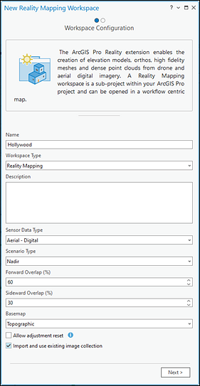
- In the Workspace Configuration pane, type a name for the workspace.
- Ensure that the Workspace Type option is set to Reality Mapping.
- Select the Sensor Data Type option that matches the data managed by the mosaic dataset from the drop-down list.
Scenario Type is automatically set based on the Sensor Data Type option selected. It is recommended that you do not change this setting.
Optionally, if Sensor Data Type is set to Aerial - Digital, adjust the Forward Overlap and Sideward Overlap values if required.
- Check the Import and use existing image collection check box, and click Next.

- On the Import Data page, set the mosaic dataset as the input for Image Collection.
- If the mosaic dataset has already been adjusted, check the This image collection is adjusted check box.
- Optionally, if the adjusted mosaic dataset has the corresponding processing data, define the Control Points, Solution Points, Solution Table, and Solution DSM inputs. These can be left blank, but certain operations will not be available, such as generating the adjustment report, performing a block adjustment, or interpolating a DEM from solution points using the DEMs wizard.
- Click Finish.
Related topics
- Reality mapping in ArcGIS Pro
- Add ground control points to a Reality mapping workspace
- Manage tie points in a Reality mapping workspace
- Perform a Reality mapping block adjustment
- Generate multiple products using ArcGIS Reality for ArcGIS Pro
- Introduction to the ArcGIS Reality for ArcGIS Pro extension
- Frequently asked questions