Available with Advanced license.
You can inspect images and edit tie points in an ortho mapping workspace.
Tie points are common objects or locations within the overlap areas between adjacent images. These points are used to improve geometric accuracy in the block adjustment. Tie points are usually computed automatically using image matching techniques. For certain cases, however, such as images that contain large bodies of water or sand, or images captured in different seasons, the automatic matching technique may not detect a sufficient number of points required for the adjustment. To address this, the Manage Tie Points drop-down menu, in the Refine category on the Ortho Mapping tab, provides tools to edit, analyze coverage, recompute, and reproject tie points. The workflow is summarized below.
Tie Point Editor
The Tie Point Editor is available from the Manage Tie Points drop-down menu. It lists tie points along with a preview section highlighting tie point locations on associated images. When opened for the first time, the Tie Point Editor uses a system-defined query to list tie points with a residual greater than 1.5 pixels, sorted in descending order. This allows the viewing of points with the highest residuals that may require editing to improve block adjustment accuracy. The total number of tie points meeting the residual query is displayed at the top of the Tie Point Editor window. The tie point list displays the first 500 points from the default query result. Additional points, in increments of 500, can be loaded to the list view by clicking the Load additional points button at the top of the window.
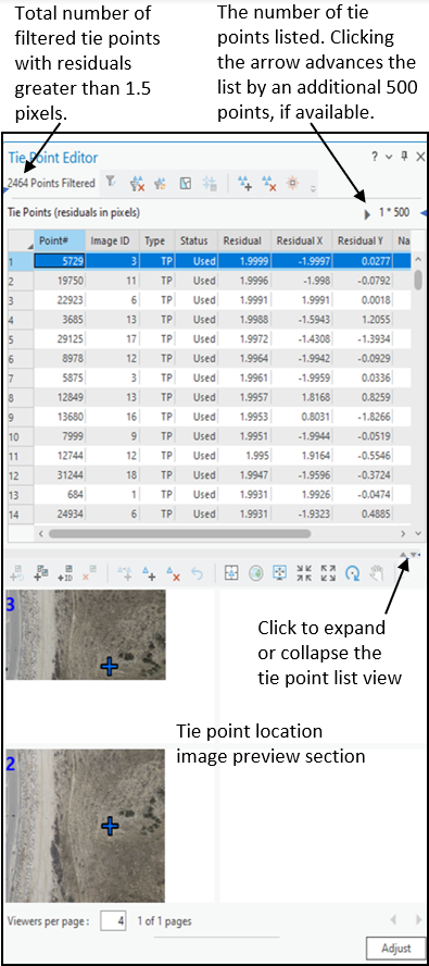
To change the query definition, click the Filter button  at the top of the window. This opens the Tie Point Filter window where you can define query filters. The following queries are supported:
- Filter by Attributes
- Filter by Images
- Filter by Current Map Extent
In the Tie Point Editor window, click the field of interest to sort the tie points in ascending or descending order. The toolbar above the list contains the following buttons that support tie point editing:
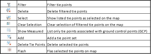
The toolbar above the image preview window contains the following buttons:

Work with the Tie Point Editor
In the Tie Point Editor window  , you can filter, add, and remove tie points to enhance image connections and adjustment accuracy. Click the Analyze Tie Points button
  to generate a coverage feature class and an overlap polygon feature class, which are added under QA/QC Data and included in the Image Inspector table. The two feature classes can help you determine whether you have enough tie points and where you need to add tie points. To add tie points for specific areas in an image collection or to recompute tie points using different parameters, click the Recompute Tie Points button
  . Generating tie point map locations can be time consuming especially when working with large projects. In this case, you can use the Reproject Tie Points button
  from the Manage Tie Points drop-down menu after the initial adjustment process.
Note:
To reproject tie point during the adjustment process, click the Reproject Tie Points button in the Adjust window.
These tools update the control points in the ortho mapping workspace. Click Adjust to incorporate changes and update the image collection.
Filter and edit tie points using an attribute query
The objective of tie point editing is to reduce relative and absolute orientation errors, and enhance derived product accuracies. Tie point editing is an iterative process that involves manually editing (repositioning, adding, and deleting) tie points, rerunning the adjustment, analyzing the adjustment residuals, and repeating the process until an acceptable outcome or error is achieved. Tie point editing is required under the following conditions:
- The reprojection error of the adjustment is greater than 1 pixel or larger than project requirements.
- An insufficient number of tie points were generated.
- The generated tie points were not well distributed.
To filter and edit tie points using an attribute query, complete the following steps:
- Click the Tie Point Editor button
 .
.The Tie Point Editor window appears, listing tie points with a residual greater than 1.5 pixels and sorted in descending order.
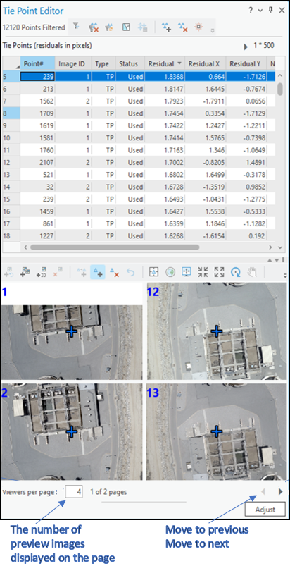
- Select a tie point of interest from the list to automatically populate the preview section with the associated images that contain the tie points.
In the Preview section, the Image ID attribute associated with the selected tie point is displayed at the top of the window.
Note:
If the tie point appears in more images than the Views per page value, the additional images are rendered on subsequent pages. Use the Move to next or previous page button to advance the Preview window to view additional images.
Reposition a tie point
To reposition an existing tie point, complete the following steps:
- Select a tie point from the list view of tie points.
- Optionally, expand the Tie Point Editor window.
- Hoover over the left or right edge of the window.
The pointer changes to a double-headed arrow.
- Click and drag the window to the new size and release the mouse button.
In the expanded preview window, the images are more interpretable. The list view is also expanded.
To view only the preview images, click the Expand button above the preview window toolbar on the right.
- Hoover over the left or right edge of the window.
- To reposition a tie point, click the Add tie point button
 , and click the new location in each image in the preview window.
The point Type attribute changes to manual tie point (MTP) and the number sign (#) replaces the Object ID number to signify the point has been edited.
- Repeat the previous steps to edit additional tie points.
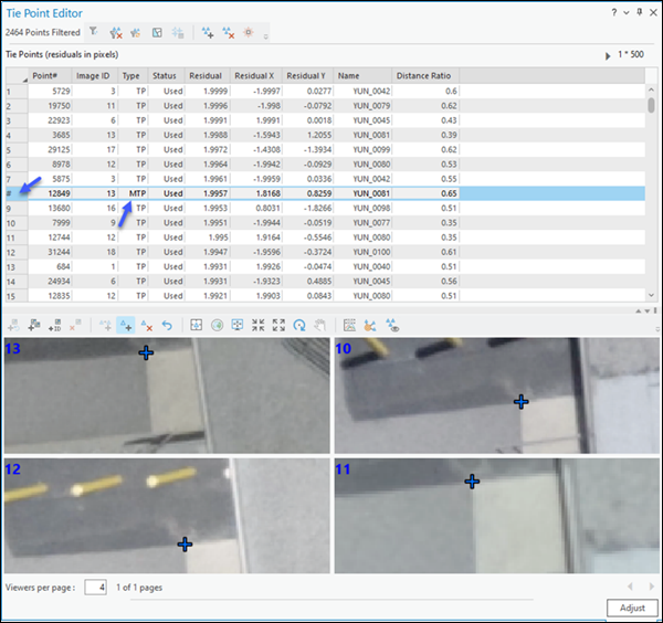
Delete tie points
To delete tie points, complete the following steps:
- Select a point or a group of points in the tie point list, and click Delete Tie Points
 .
. - To expand the tie point list view so more points can be analyzed and simultaneously edited, click the Collapse button above the preview window toolbar on the right.
- Alternatively, delete multiple points by filtering the tie points and clicking the Delete filtered point sets button
 .
.
View and edit ground control tie points only
Tie points associated with ground control points (GCPs) can also be filtered and edited using the Tie Point Editor.
To filter and edit tie points associated with GCPs, complete the following steps:
- In the Tie Point Editor window, click Show Measured
 button to list only GCP tie points.
The tie point list displays measured points designated as Type or MTP.
- Select a tie point ID in the list to load all associated images in the preview window.
- Reposition the GCP on the images in the preview window.
Occasionally, the position of a tie point in all overlapping images is correct, but the residual for the point is high. This may be due to the influence of surrounding tie points with poor positional accuracy. In this case, it is recommended that you leave the GCP tie point positions unchanged and edit the surrounding points.
- Click the Show Measured button to return to the previous filter in the Tie Point Editor.
Add a tie point set
To add a tie point set, complete the following steps:
- At the top of the Tie Point Editor window, click the Add a point set button
 .
.A generic point is added with a system defined Point ID value.
- If no images are displayed in the image preview section, click the Load Images button
 .
.All associated images are loaded into the preview windows.
- To load the overlapping images into the preview windows, in the 2D map with the mosaic dataset active, draw a rectangle on the map where you want to add a tie point.
To add tie points manually, click the matching feature in each image displayed in the preview windows. You can also add points using a semiautomated process.
- If no images are displayed in the image preview section, click the Load Images button
- Click the Auto Add button
 , and click a feature in the top left image to place a tie point.
The matching tie point location is automatically detected in the other overlapping images.
- When you're finished adding tie points, click the Adjust button in the Tie Point Editor window to rerun the adjustment and incorporate the changes.
- When the readjustment completes, review the Reprojection Error value if working with drone, digital aerial, or scanned aerial data. If working with satellite imagery, review the RMSE_TIE_IMAGE(x,y) value.
Updated results are also displayed in the Tie Point Editor point list. If the results are not acceptable, repeat the tie point editing steps above.
Filter and edit tie points using an attribute query
To edit tie points based on a user-defined query, complete the following steps:
- On the toolbar at the top of the Tie Point Editor window, click the Filter button
 .
.The Tie Point Filter window appears.
- In the Tie Point Filter window, change the filtering parameters as needed and click OK.
Listing points that meet the query results are displayed in the Tie Point Editor window.
- Edit the tie points using the steps in the Filter and edit tie points using an attribute query section above.
Edit tie points using a specific point ID
To edit a tie point, or tie point set, based on a specific point ID, complete the following steps:
- On the toolbar at the top of the Tie Point Editor window, click the Filter button.
The Tie Point Filter window appears.
- In the Tie Point Filter window, in the Point ID text box, provide the single tie point ID, or multiple tie point IDs separated by commas, of the points to edit.
Optionally, uncheck the Residual check boxes in the Attributes section. When the boxes are unchecked, the query is run based on the residual criteria in the Attributes section.
- Click OK to run the query.
Tie points that meet the query results are displayed in the Tie Point Editor window.
- Edit the tie points using the steps in the Filter and edit tie points using an attribute query section above..
Edit tie points using the image ID
To edit tie points in a single image or multiple images using the image ID, complete the following steps:
- On the toolbar at the top of the Tie Point Editor window, click the Filter button.
The Tie Point Filter window appears.
- In the Tie Point Filter window, in the Point ID text box, provide the single image ID, or multiple image IDs separated by commas, of the points to edit.
Optionally, uncheck the Residual check boxes in the Attributes section. When the boxes are unchecked, the query is run based on the residual criteria in the Attributes section.
- Click OK to run the query.
Tie points that meet the query results are displayed in the Tie Point Editor window.
- Edit the tie points using the steps in the Filter and edit tie points using an attribute query section above.
Filter and edit tie points by images
To edit tie points based on images, complete the following steps:
- On the toolbar at the top of the Tie Point Editor window, click the Filter button.
The Tie Point Filter window appears.
- In the Tie Point Filter window, check the Images option.
- Click OK to run the query.
A list of images that meet the query results is displayed in the Tie Point Editor window.
- Select an image to populate the Tie Points section with all associated tie points.
The selected image is highlighted and zoomed to in the 2D map window.
- Select a tie point to populate the image preview section with all associated images.
- Edit the tie points using the steps in the Filter and edit tie points using an attribute query section above.
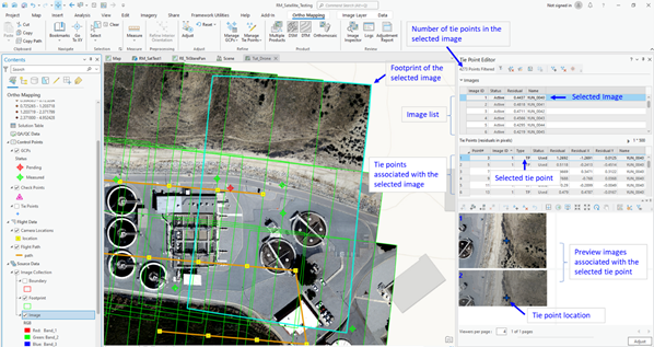
Filter and edit tie points by the current map extent
To edit tie points based on the current map extent, complete the following steps:
- In the 2D map view, zoom to the area of interest.
- On the toolbar at the top of the Tie Point Editor window, click the Filter button.
The Tie Point Filter window appears.
- In the Tie Point Filter window, check the Current map extent check box.
- Click OK to run the query.
A list of tie points that meet the query results is displayed in the Tie Point Editor window.
- Edit the tie points using the steps in the Filter and edit tie points using an attribute query section above.
Add tie points to include dropped images
Occasionally, an image is dropped during block adjustment due to insufficient tie point coverage. This can occur when neighboring images do not meet minimum overlap requirements, or when much of the image is covered by clouds or water. You can reactive dropped images and include them in the block adjustment by adding tie points manually.
To reactivate dropped images, complete the following steps:
- On the toolbar at the top of the Tie Point Editor window, click the Filter button.
The Tie Point Filter window appears.
- To load all images in the project, uncheck the Type and Residual check boxes in the Attribute section of the Tie Point Filter window.
This ensures that the attribute query parameters do not influence the image query.
- Check the Images option.
- Click OK to run the query.
A list of the images meet the query result is displayed in the Tie Point Editor window.
- Edit the tie points using the steps in the Filter and edit tie points using an attribute query section above.
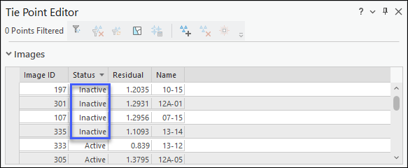
- Click the Status field name to sort the image list in descending order.
Inactive images are displayed at the top of the list.
- Select an inactive image from the image list, right-click, and click Activate.
The image Status value changes to Active. To support tie point determination, the footprint of the selected image is highlighted and zoomed-in in the 2D map window.
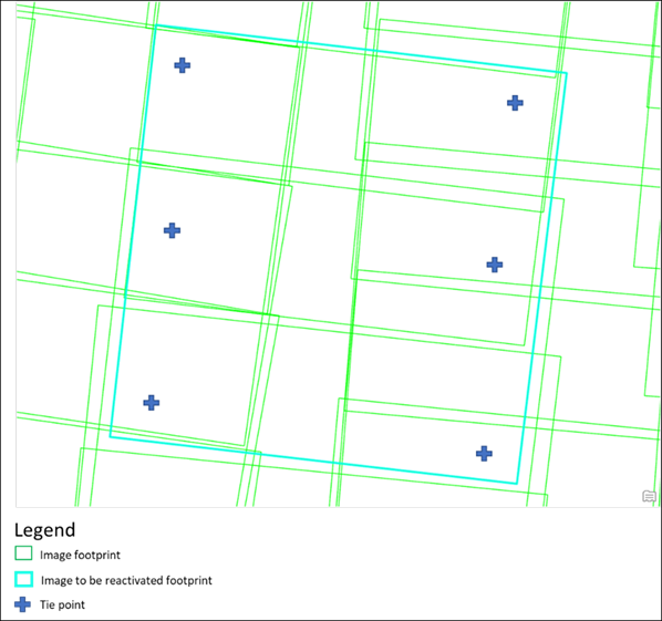
- Click the Add a Point Set button
 to add a point set template with a system-generated point ID.
 The point ID becomes visible in the tie points list after the first tie point has been placed on the image.
- In the 2D map, zoom to the area to place the first tie point.
- Click the Load Images button on the toolbar to ensure that the appropriate images are listed in the Preview section of the Tie Point Editor window.
- In the 2D map window, draw a box around the area where a tie point is to be selected.
All overlapping images are loaded into the Preview section of the Tie Point Editor window. The image being reintegrated is at the upper left.
- Click the Auto Add button
 to add a tie point, and click a feature in the upper left image to place the point.
Additional tie points are automatically selected in overlapping images. The selected tie points are added to the Tie Points list with a Type value of MTP.
- Click the Synchronize Scale button to review the positional accuracy of the selected tie points in all overlapping images.
This matches the zoom scale of all preview images with that of the upper left image.
- Optionally, click the Add tie point button
 to manually add or reposition tie points in overlapping images if the automatic correlation failed.
 - Click the Add a Point Set button
 to select additional, well-distributed tie points using the method described above.
 - Click the Show Manual Tie Points button
 to help identify where manual tie points were previously placed in the reintegrated images.
 - When you have selected all six, well-distributed tie points, click Adjust to integrate the points into the adjustment..
- Review the adjustment log or the residuals in the Tie Point Editor window to ensure that the image is no longer listed as inactive and the accuracy is acceptable.
Note:
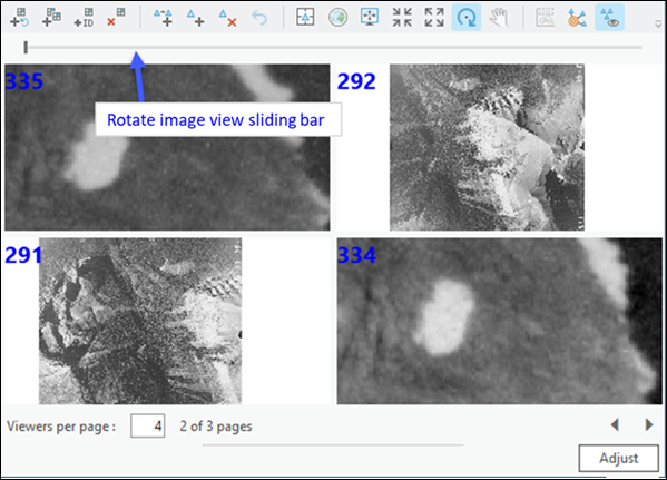
If the tie point appears in more images than the Viewers per page value, the additional images are rendered on subsequent pages. Use the Move to next or previous page button to advance the Preview window to view additional images.
 . This displays a sliding bar below the preview image toolbar. Click in the view to be rotated, and drag the sliding bar to rotate the selected view image. Repeat the steps above to rotate other views as necessary. Click the Rotate button to deactivate the functionality when you're finished.
Filter images using the Image Inspector pane
The Image Inspector pane in the Review group under the Ortho Mapping tab can also be used to filter images that require tie point editing. You can use the Image Inspector pane at any time in the ortho mapping workflow. Perform the block adjustment before tie point and adjustment statistics are available for each image.
To filter images using the Image Inspector pane, complete the following steps:
- From the Manage Tie Points drop-down menu, click the Analyze Tie Points tool to generate tie point counts and coverage for each image in the collection.
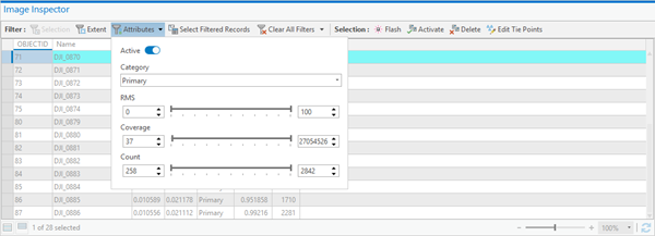
- Click the Attributes tool and filter the list of images by adjusting the ranges for RMS, tie point coverage, and tie point count.
You can also filter images using the Extent tool to capture points in the current display.
- Inspect individual images by selecting an image from the list.
The image appears in the preview window next to the image list, where you can view image information, including adjustment statistics, exterior orientation, and interior orientation. Some images may be dropped during the adjustment.
- Click the Attributes tool and select Inactive from the drop-down menu to filter dropped images.
- Click the Activate or Delete buttons to add or remove an image from the adjustment.
- Once you identify the images or tie points you want to edit, select an image, and click the Edit Tie Points tool in the Image Inspector pane to begin editing tie points for the current image.
