When building network diagrams, any container, content features, or objects detected among the initial network elements or added by a diagram rule are processed in the same way.
Linear, point, and polygon containers in network diagrams
Contents and containers in the utility network or trace network
Network features or network objects that contain other network elements are called containers, while the network features and network objects that are contained are called contents.
There are three types of containers among the elements that compose a network:
- Linear containers are network line features or network edge objects—for example, structure lines and structure edge objects.
- Point containers are network point features or network junction objects—for example, assembly devices and structure junction objects.
- Polygon containers are network polygon features on the map—for example, structure boundaries.
Whatever its type, a container is generally related to a set of contents with those relations respecting the utility network or trace network containment rules. Moreover, a container can contain another container.
Contents and containers in network diagrams
In general, network diagrams are generated from a set of network features or network objects selected on the map. Those input network elements are called initial elements for diagram building.
Whether or not they are initial elements for diagram building, containers and contents are often visible in the generated network diagrams. Moreover, when contents are visually represented in a diagram, their related container is also represented in the diagram by default.
Note:
A container can exist in a diagram without any of its contents being represented. For example, this happens when none of the container's contents are part of the diagram or when its contents are part of the diagram but have been collapsed.
Linear containers
Linear containers in the network are always line features in the network diagram. They exist in any diagram in which they represent network linear containers, such as in the following situations:
- Either initial or added through rules during diagram building
- Automatically added to the diagram during its build because some or all of their contents are initial or added through rules during the diagram building
Point containers
Point containers represent junctions in the network and are either points or polygons in network diagrams.
- Point containers are kept as points in the generated diagram in the following two situations:
- When they are initial containers without any of their related contents
- When those containers are collapsed in the diagram
- Point containers become rectangle polygons that display around their contents in the generated diagram in the following two situations:
- When they are automatically added to the diagram during its build because some or all of their contents are initial or added through rules during the diagram building
- When those containers are expanded in the diagram
Polygon containers
Polygon containers representing structure boundaries in the network are either points or polygons in network diagrams.
- Polygon containers become diagram points in the following two situations:
- When they are initial containers without any of their related contents
- When those containers are collapsed in the diagram
Note:
When features in the generated diagram display at their geographic positions, each container polygon feature transformed as a diagram point is placed at the centroid of the network polygon feature.
- Polygon containers are represented as rectangle polygons that display around their contents in the following two situations:
- When they are automatically added to the diagram during its build because some or all of their contents are initial or added through rules during the diagram building
- When those containers are expanded in the diagram
Contents and containers in network diagrams based on the three installed templates
At its creation, any utility network or trace network has three diagram templates that are ready to use to generate network diagrams: Basic, ExpandContainers, and CollapseContainers.
Basic diagrams
The Basic template is configured with two rules only: Add Connectivity Associations and Add Structural Attachments. It allows you to generate diagrams that show how the selected input network elements are connected to each other with respect to the network topology. This section focuses on the way this Basic process works with containers and contents:
- Any container element that is initial for the diagram generation is represented in a Basic diagram.
A point container feature or a container junction object in the network is represented as a point feature in the Basic diagram unless some or all of its contents also exist among the initial network elements used for the diagram generation. In that case, the point container feature or container junction object becomes a rectangle polygon container in the Basic diagram and draws around all of its related contents in the resulting diagram.
A polygon container feature in the network is systematically transformed into a point feature in the Basic diagram unless some or all of its contents also exist among the initial network elements used for the diagram generation. In that case, the polygon container feature is transformed into a rectangle polygon container in the Basic diagram and draws around all of its related contents in the resulting diagram.
A linear container feature or a container edge object in the network is represented as a line feature in the Basic diagram—whether or not its related contents are initial for the diagram generation.
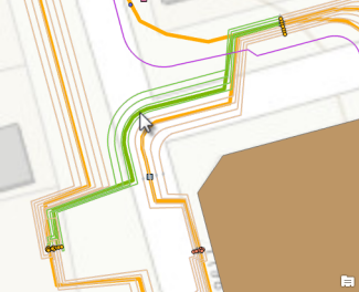
Graphic A1—Select a sample linear container on the map. 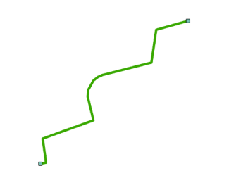
Graphic A2—A Basic diagram is generated from this sample linear container. Graphic A1 shows a linear container used as the only input in the network map for the Basic diagram generation.
Graphic A2 shows how this linear container and the two point containers it is connected to in the network are represented in the resulting Basic diagram. Since none of its own contents or any of the contents related to its extremity point containers were selected as input on the map, those contents are not represented in the Basic diagram.
- Edges in a network diagram must have end junctions. Regardless of whether those junctions are part of the original selection set used to generate a diagram, the junctions end up as part of the diagram. When those junctions are contents, their related containers are also automatically added to the diagram whether or not they are initial, and depending on their nature, they are represented as follows:
- Spatial containers with a point or polygon geometry and nonspatial containers corresponding to container junction objects in the network are rectangle polygon features in the diagrams, represented as rectangles around each end junction.
- Spatial containers with a linear geometry and nonspatial containers corresponding to container edge objects in the network are line features in the diagrams.
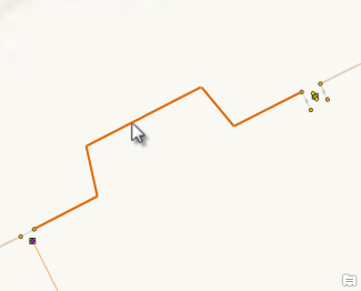
Graphic A3—Select a sample noncontent line on the map. 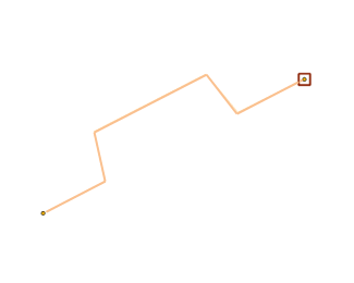
Graphic A4—A Basic diagram is generated from this sample noncontent line. Graphic A3 shows a network line feature used as the only input in the network map for the Basic diagram generation. The line is a standard feature; that is, it is neither content nor a container.
Graphic A4 shows how this network line feature and the two network point features it is connected to are represented in a Basic diagram. Since one of its point extremities—the one on the right—is content, it is represented in the diagram with its container, the rectangle polygon around it.
- Any content feature or object that is initial for the diagram generation is represented in a Basic diagram.
Its container is automatically added to the diagram whether or not it is initial.
A point container feature or a container junction object in the network is represented as a rectangle polygon feature in the Basic diagram and draws around all its related contents that are represented in the diagram. A linear container feature or a container edge object in the network is represented as a line in the Basic diagram.
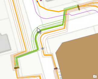
Graphic A5—Select a sample content line on the map. 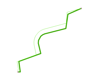
Graphic A6—A Basic diagram is generated from this sample content line. Graphic A5 shows a content line used as input on the map for the Basic diagram generation.
Graphic A6 shows how this content line is represented in the resulting Basic diagram. Its related linear container is also represented in the diagram—this is the larger green line. Moreover, since the initial content line connects points that are contents of structure junctions, those structure junction containers are also represented in the diagram: they display as rectangle polygon features that are drawn around the initial content line's extremities.
ExpandContainers diagrams
The ExpandContainers template is configured to chain the following rules:
- An Expand Container rule, which systematically expands any containers selected as input for diagram generation. All the linear containers, point containers, and polygon containers are expanded in the ExpandContainers diagram and show their entire related contents.
- An Add Connectivity Associations rule, which allows the representation of all connectivity associations of the network for which both the from and to junctions are present in the diagram. Those connectivity associations are displayed as diagram edges that connect the related from and to diagram junctions in the generated diagram.
- An Add Structural Attachments rule, which allows the representation of all structural attachments of the network for which both the from and to junctions are present in the diagram. Those structural attachments are displayed as diagram edges that connect the related from and to diagram junctions in the generated diagram.
Regarding containers and contents, ExpandContainers diagrams have the following characteristics:
- Any container, whether initial or not, for diagram building is represented in the resulting diagram with all its contents.
A point container feature or a container junction object in the network always becomes a rectangle polygon container in the ExpandContainers diagram and draws around its related contents, which are all represented in the diagram.
A linear container feature or a container edge object in the network is a line feature in the ExpandContainers diagram. All its related contents are added to the diagram.

Graphic B1—Select a sample linear container on the map. 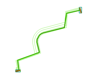
Graphic B2—The ExpandContainers diagram is generated from this sample linear container. Graphic B1 shows a linear container used as the only input in the network map for the ExpandContainers diagram generation.
Graphic B2 shows how this linear container and the two point containers it is connected to are represented in the resulting ExpandContainers diagram. All its own contents and all the contents related to its extremity point containers are represented in the diagram.
- Any network feature or network object that is content, whether initial or not, for diagram building is represented in an ExpandContainers diagram with its container and all the other contents that share the same container.

Graphic B3—Select a sample content line on the map. 
Graphic B4—The ExpandContainers diagram is generated from this sample content line. Graphic B3 shows a content line used as input on the map for the ExpandContainers diagram generation.
Graphic B4 shows the generated ExpandContainers diagram with this content line; its related linear container and all its related contents are also represented in the diagram. Moreover, since the initial content line connects points that are themselves contents of structure junctions, those container structure junctions are represented in the diagram; they display as rectangle polygon features that are drawn around all their own related contents.
CollapseContainers diagrams
The CollapseContainers template mainly collapses any contents that exist in the diagram, regardless of the geometry of their related containers. The template configuration runs the following rules sequentially:
- An Expand Container rule, which systematically expands any point containers and polygon containers selected as input for diagram generation. All their related contents are added to the diagram.
- An Add Connectivity Associations rule, which allows the representation of all connectivity associations of the network for which both the from and to junctions are present in the diagram. Those connectivity associations are displayed as diagram edges that connect the related from and to diagram junctions in the generated diagram.
- A Collapse Container rule, which collapses any contents that exist in the diagram.
- An Add Structural Attachments rule, which allows the representation of all structural attachments of the network for which both the from and to junctions are present in the diagram. Those connectivity associations are displayed as diagram edges that connect the related from and to diagram junctions in the generated diagram.
- Any point container or linear container, whether initial or not, for diagram building is represented in a CollapseContainers diagram in the same way it is represented on the map. However, polygon containers in the network are systematically transformed as point features in the generated diagram.

Graphic C1—Select a sample linear container on the map. 
Graphic C2—A CollapseContainers diagram is generated from this sample linear container. Graphic C1 shows the linear container—the wide, green line —used as the only input in the network map for the CollapseContainers diagram generation.
Graphic C2 shows how this linear container is represented in the resulting ExpandContainers diagram. It is represented as a diagram edge without any of its contents. The two container structure junctions it connects are also represented in the diagram with none of their related contents.
- Any network feature or network object that is content, whether initial or not for diagram generation, is never represented in a CollapseContainers diagram. It is systematically collapsed onto its related container.
Any polygon container feature is systematically transformed as a collapsed junction in the diagram.
Any point container feature is represented as a collapsed junction in the diagram.
Any noncontent line feature or edge object that might connect content point features is systematically reconnected to connect its related collapsed diagram junction.

Graphic C3—Select a sample content line on the map. 
Graphic C4—A CollapseContainers diagram is generated from this content line. Graphic C3 shows the content line used as input on the map for the CollapseContainers diagram generation.
Graphic C4 shows the resulting diagram where this content line is not represented. Its related linear container has been added to the diagram during the Elementary Build phase, and this container collapsed the content line in the resulting diagram. Moreover, since the initial content line connects network point features that are themselves contents of structure junctions, those content points and their related containers were also present in the diagram at the end of the Elementary Build phase. When the Collapse Container rule run, the containers transformed into point containers that collapsed the content connection points.

Graphic C5—Select a sample noncontent line on the map. 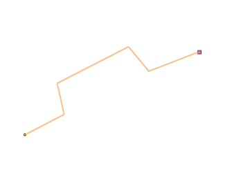
Graphic C6—A CollapseContainers diagram is generated from this noncontent line. Graphic C5 shows the line used as the only input in the network map for the CollapseContainers diagram generation. The line is a standard feature; that is, it is neither content nor a container.
Graphic C6 shows how this standard line and the two point features it is connected to are represented in a CollapseContainers diagram. Since one of its junction extremities—the one on the right—is content, the line no longer connects this content in the resulting diagram. It directly connects the related container, which was represented as a rectangle polygon at the end of the diagram Elementary Build phase and transformed as a point container collapsing the content junction during the Collapse Container rule process.