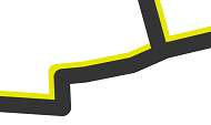
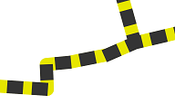
Stroke symbol layers are components of symbols that draw lines and outlines. They are most often used in line symbols or in polygon symbols as outlines.
Types of strokes
Strokes can be one of the following three types:
Solid stroke |  | Draws linear geometry with a single solid color and width |
Picture stroke |  | Draws linear geometry with an image file |
Gradient stroke |  | Draws linear geometry with a linear color gradient |
Stroke symbol layers can also be used in mesh symbols to draw the edges of multipatch features and 3D object scene layers. In this context, stroke symbol layers can only be of Solid stroke type, and you cannot set any property other than color.
Use the drop-down menu within each layer as they are listed in the Format Symbol mode of the Symbology pane, on the Properties tab, on the Layers tab  to set the layer type.
Solid stroke symbol layers
Solid stroke symbols contain two main properties: Color, which can be partially transparent, and Width.
Picture stroke symbol layers
Picture stroke symbol layers use an image file to draw linear geometry. In the Format Symbol mode of the Symbology pane, on the Properties tab, on the Layers tab  , expand the Appearance group. Click Picture to browse to an image file. Valid file formats are *.bmp, *.jpg, *.png, and *.gif. Adjust the Quality, Tint, and Size properties as necessary.
Tip:
Set the Tint property to white, which is the default setting, to draw the image in its default colors. Setting this property to no color causes no image to be drawn at all.
Each of the Quality settings corresponds to a different resampling method:
- Draft—Nearest-neighbor resampling
- Picture—Bilinear resampling
- Text—Anisotropic resampling
Click Reset size to revert the image to its default size.
Gradient stroke symbol layers
Gradient stroke symbol layers use a color scheme to draw line geometry. The direction of the gradient follows the direction of the line.
In the Format Symbol mode of the Symbology pane, on the Properties tab, on the Layers tab  , expand the Appearance group. Click the Color Scheme drop-down menu to choose a color scheme or choose a start and end color from the color pickers. Only continuous color schemes can be applied to gradient stroke symbol layers. If necessary, reverse the current scheme by clicking the Flip color scheme button
  . Adjust the stroke Width value as necessary.
To use a different color scheme, click the color scheme menu and click More color schemes to access color schemes in the project styles. If you need a different color scheme not available in a style, click the color scheme menu and click Color scheme properties to open the Color Scheme Editor dialog box. Construct the color scheme as necessary. To save the custom color scheme for reuse, click Save to a style. Click OK to return to the Format Symbol pane.
Stroke symbol layers in 3D
When a symbol with a stroke is used in a 3D context (such as in a layer in the 3D Layers section of a scene), you can specify the cross-section shape from the Profile property. The profile choices include the following:
- Tube
 —A stroke with a circular cross-section. The diameter of the circle is set by the Width property.
 - Strip
 —A flat stroke lying parallel to the surface. The width of the strip is set by the Width property, and it has no height.
 - Wall
 —A flat stroke lying perpendicular to the surface. The width of the wall is set by the Width property, and it has no thickness.
 - Square
 —A stroke with a square cross-section. Both dimensions of the square are set by the Width property.
 - Rectangle
 —A stroke with a rectangular cross-section. The two dimensions of the rectangle are set by the Width and Height properties. If either dimension is set to 0, the stroke will not draw.
Caution:
When a stroke with a Strip profile is used as a polygon outline in 3D, it draws as 1pt wide regardless of the stroke width setting. To draw a thicker polygon outline that respects the stroke width setting, change the profile to Tube.
When the Tube, Square, or Rectangle profiles are used, you can also set the Anchor property as follows:
- Center—The center of the 3D stroke is aligned to the geometry. Note that in some cases, the stroke may be half-buried into the surface.
- Bottom—The bottom of the 3D stroke is aligned to the geometry.
- Top—The top of the 3D stroke is aligned to the geometry. Note that in some cases, the stroke may be buried beneath the surface.
The actual placement of the stroke in 3D space depends on both the Anchor property of the symbol and the elevation properties of the layer.
Stroke symbol layer properties
Both types of stroke symbols have additional properties that define the appearance of the symbol in which they are contained.
Offset strokes

The graphical stroke can be drawn perpendicularly offset relative to the geometry. Define the offset distance from the Offset property in the Offset effect group. Choose a Join style—Bevel, Round, or Miter—to control how the joins are handled at the offsets.
Offsets in a stroke symbol layer are symbol effects with a default definition of no offset. This is a convenience to adjust a stroke offset without having to add an effect. This effect can be managed in the same way as any symbol effect in a symbol layer. When symbols with offset stroke layers draw, the offsetting is processed before any dashes present on the stroke.
Dashed strokes

As with stroke offsets, stroke dashing is also handled with an available Dash effect with a default definition of no dash (a solid, uninterrupted stroke). This effect is added as a convenience to stroke symbol layers and can be managed in the same way as any other symbol effect.
Choose a dash from the Dash type pull-down gallery, and adjust the Dash template values as necessary. Each dash value in the template represents the next segment of the dash—for example, a dash template of 7 3 would return a 7-point stroke followed by a 3-point gap, followed by another 7-point stroke and 3-point gap, and so on.
Caps and joins on strokes
The properties in the Caps & Join group define how the stroke should draw at the ends of strokes (caps) and at junctures (joins).
| Caps | |
|---|---|
Butt—Line symbols stop squarely and exactly at the endpoints. |  |
Round—Semicircles extend past the endpoints. |  |
Square—Line symbols extend half the symbol's width past the endpoints. |  |
| Joins | |
|---|---|
Bevel—Corners are clipped at junctures, especially at sharp angles. |  |
Round—Semicircles are drawn at endpoints. |  |
Miter—Symbol edges are extended, creating pointed angles. |  |
Patterns on strokes
For gradient strokes only, the Pattern type can be adjusted to provide a discrete or continuous stroke style.
Continuous—The gradient follows a constant change in color. |  |
Discrete—The gradient is a specified number of intervals. |  |