Description
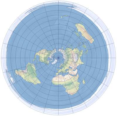
The azimuthal equidistant projection preserves both distance and direction from the central point. The world is projected onto a flat surface from any point on the globe. Although all aspects are possible (equatorial, polar, and oblique), the one used most commonly is the polar aspect, in which all meridians and parallels are divided equally to maintain the equidistant property.
It is believed that the projection was first used by the Egyptians for star charts. It is available in ArcGIS Pro 1.0 and later and in ArcGIS Desktop 8.0 and later.

Projection properties
The subsections below describe the azimuthal equidistant projection properties.
Graticule
Azimuthal equidistant is an is azimuthal projection.
In the polar aspect, the meridians project as straight lines originating at the pole, and angles between them are true. The parallels are shown as equally spaced concentric circular arcs. All graticule line intersections are 90 degrees. The opposite pole is projected as a circle and presents the edge of the map. The graticule is symmetric.
In the equatorial aspect, the equator and central meridian are projected as two perpendicular straight lines. Two meridians, 90 degrees east and west of the central meridian, project as a circle. Other meridians are complex curves, equally spaced along the equator. All parallels are equally spaced along the central meridian and the meridians 90 degrees east and west of the central meridian. Their complex curves are concave toward the nearest pole. Both poles project as points. The antipodal point of the projection's center projects as a circle and presents the edge of the map. The graticule is symmetric across the equator and the central meridian.
In the oblique case, only the central meridian and antimeridian project as straight lines. Other meridians and parallels are complex curves. Meridians intersect at poles, which are projected as points. Parallels are equally spaced along the central meridian. The antipodal point of the projection's center projects as a circle and presents the edge of the map. The graticule is symmetric across the central meridian.
Distortion
This projection preserves both distance and direction from the central point. Scale is true only along straight lines radiating from the center of the map. On polar aspect, this is along the meridians. Otherwise, shape, scale, and area distortion increase outward from the center point. Distortion symmetry follows the symmetry of the graticule.
Usage
Although the projection can display the entire globe, its practical usage is often limited to a hemisphere. This projection is most commonly used for maps of polar regions and routes of air and sea navigation with appropriate aspect. The oblique aspect is sometimes used for important cities and their surrounding area.
Variants
There are two variants available in ArcGIS.
- The azimuthal equidistant variant has been available since ArcGIS Pro 1.0 and ArcGIS Desktop 8.0.
- The azimuthal equidistant auxiliary sphere variant has been available since ArcGIS Pro 1.0 and ArcGIS Desktop 9.3. This variant does not support the ellipsoid and uses sphere-based equations with a sphere specified by a user using the Auxiliary Sphere Type parameter. True distance and direction from the central point is not maintained when an ellipsoid is used in this variant.
Limitations
The azimuthal equidistant variant is the only variant of this projection that supports ellipsoids.
Parameters
Azimuthal equidistant parameters are as follows:
- False Easting
- False Northing
- Central Meridian
- Latitude Of Origin
Azimuthal equidistant auxiliary sphere parameters are as follows:
- False Easting
- False Northing
- Central Meridian
- Latitude Of Origin
- Auxiliary Sphere Type, with values as follows:
- 0 = use semimajor axis of the geographic coordinate system
- 1 = use semiminor axis
- 2 = calculate and use authalic radius
- 3 = use authalic radius and convert geodetic latitudes to authalic latitudes
Note:
If the geographic coordinate system uses a sphere, the Auxiliary Sphere Type uses the radius of the sphere in all four cases.
Sources
Snyder, J. P. (1987). Map Projections: A Working Manual. U.S. Geological Survey Professional Paper 1395. Washington, DC: United States Government Printing Office.
Snyder, J. P. (1993). Flattening the Earth. Two Thousand Years of Map Projections. Chicago and London: University of Chicago Press.
Snyder, J. P. and Voxland, P. M. (1989). An Album of Map Projections. U.S. Geological Survey Professional Paper 1453. Washington, DC: United States Government Printing Office.