Hydro-flattening is the process of leveling water bodies in elevation models. It involves ensuring that lakes and reservoirs are at a constant height, and rivers are level from bank to bank while simultaneously flowing consistently downslope. Hydro-flattening is performed for both analytic and cartographic purposes. It can improve flow modeling, and ensures that water bodies in derived hillshades look flat, contours don't cross over the middle of lakes, and contours cross rivers in a clean fashion, nearly perpendicular to flow direction.
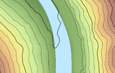
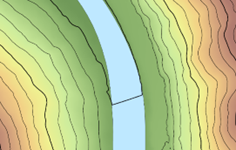
While it's possible to perform hydro-flattening on an existing digital elevation model (DEM) as a post process, it's generally better to do it when interpolating the DEM from the source vector data. This is because it's a little easier to control the transition zone between ground and water, avoiding sharp discontinuities. The workflow described below handles the flattening as part of the DEM production using a LAS dataset.
Prerequisites
To produce hydro-flattened DEMs, you need aerial lidar, and water shorelines for lakes, reservoirs, and rivers, all represented as polygons. Lakes and reservoirs larger than 0.8 hectares, and rivers 30 meters or wider in average width, are generally treated. Smaller features are usually skipped. Individual rivers are modeled by individual polygons. River networks can also be represented using individual polygons, although more complex in shape. For rivers, you also need pour direction lines that are used to indicate primary locations of inflow and outflow. These lines may already be available in existing stream-line data (see the Resources section below). If not, they can be made manually.
Create a LAS dataset with classified ground and water
To start, create a LAS dataset from your aerial lidar. If your lidar has yet to be classified for ground, you can use the Classify LAS Ground tool.
Water points also must be classified. If the lidar classification already includes water, the proper source of water polygons that are needed in a later workflow will be those used for the water classification process. Review the breakline data associated with the lidar project for these polygons. If water is not classified, find water polygons from a reliable source and use them with the Set LAS Class Codes Using Features geoprocessing tool, with points filtered to ground, to assign the class 2 points inside the polygons as class 9 for water. One possible source for water polygons in the U.S. is NHDPlus. The polygons can also be manually collected from orthoimagery.
Work with lakes and reservoirs
Lakes and reservoirs are flattened by enforcing constant height polygons as constraints in the LAS dataset. The interpolation process used to convert the LAS dataset to a raster DEM will enforce the constraints.
If you don't have water height information for the polygons, you can get it from the lidar. To do this, filter the LAS dataset to ground and use the Interpolate Shape geoprocessing tool with your polygons and the Method parameter set to Conflate Nearest Z. This will assign ground height to the vertices around the perimeter of each polygon. The result is likely to undulate up and down though. It's not going to be perfectly flat. What you need to do is find the minimum ground height around the polygon and use that as the shoreline height for the polygon. Use the Add Z Information geoprocessing tool to add the lowest z-value for each polygon as an attribute. You can then use the Copy Features geoprocessing tool, with z-value disabled in the tool environment, to remove the z-values from the vertices while retaining the Min Z attribute.
Once you have water body polygons with height, add them to the LAS dataset using the Add Files To LAS Dataset geoprocessing tool as surface constraints using the Min Z attribute as the Height Fieldvalue and hardline as the Surface Feature Type value. The hardreplace value can also be used, but it is more costly from a performance perspective. As long as there aren't any ground points inside the polygons, and water points are excluded during interpolation, the hardline type is sufficient.
Work with rivers
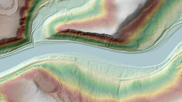
Rivers are flattened by making them level from bank to bank, while maintaining downward flow, and enforcing them as constraints in the LAS dataset. The interpolation process used to convert the LAS dataset to a raster DEM will enforce the constraints. Proper conditioning of the river heights is more complicated than for constant height polygons.
If you don't have water height information for the polygons, you can get it from the lidar. To do this, filter the LAS dataset to ground and use the Interpolate Shape geoprocessing tool with your polygons and the Method parameter set to Conflate Nearest Z. This will assign ground height to the vertices around the perimeter of each polygon. There are likely to be undesirable undulations. They may go up and down and not be level from one side of the river to the other. Use the Enforce River Monotonicity geoprocessing tool to make height adjustments, so the necessary conditions are met. This tool requires pour direction lines in addition to the polygons.
Pour direction lines are 2D features used to indicate proper flow direction for the Enforce River Monotonicity tool. The portion of the polygon representing the beginning of the river must have a pour line touching it. That line also must be oriented in the proper direction of flow, so its last vertex must be the one that connects to the polygon. The location of the polygon representing the end of the river must also have a pour line touching it, oriented in the proper direction, with its first point being the one touching the polygon. Each river must have at least two pour direction lines, one that defines inflow, and the other that defines outflow. These pour direction lines can be long or short, with many vertices or few. They must touch the river polygon boundary and be oriented properly. Use the feature editor to ensure that they touch through snapping. Use symbology to visually confirm line direction. Symbols that draw lines with arrows work for this.

Once you have the ground height around the river polygons, and the pour direction lines, use the Enforce River Monotonicity tool to adjust the height to ensure that the river flows downhill while being level from bank to bank across the river. The river can be flat along some stretches, but it is never allowed to go up. The output of this tool is a collection of 3D polylines. The tool does not output polygons because it's more efficient to enforce a collection of lines of limited size and extent into the surface than large polygons that may have a large extent with many vertices.
The output from the Enforce River Monotonicity tool is added to the LAS dataset using the Add Files To LAS Dataset geoprocessing tool as surface constraints using the Shape.Z attribute for the Height Field value and hardline as the Surface Feature Type value. For these constraints to work properly when constructing a DEM or a digital terrain model (DTM), ensure that there are no ground points inside the river areas, and exclude water points during interpolation.
Work with river networks
River networks are handled similarly to rivers. The main difference is that for river networks, a collection of connected rivers is modeled using a single polygon.

Each primary location of inflow and outflow must be represented using pour direction lines. For example, in the case of multiple tributaries flowing into a larger river, there will be an inflow pour line at the top of each tributary and a single output pour line at the bottom of the larger river they're connected to.
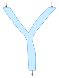
As with rivers, the output from the Enforce River Monotonicity tool is added to the LAS dataset using the Add Files To LAS Dataset tool as surface constraints using the Shape.Z attribute for the Height Field value and hardline as the Surface Feature Type value.
Shoreline transition
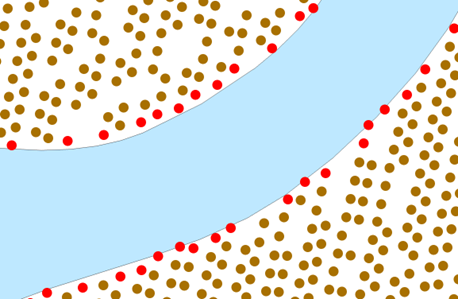
Some lidar ground points may be nearly coincident with water polygon boundaries. This can result in undesirable, sharp discontinuities at the land or water interface. To alleviate this, buffer the water polygons a short distance (for example, 0.3 meters) and use the buffered polygons to reclassify ground points to class 20, which is ignored ground by LAS classification standards. Excluding them while interpolating a raster DEM will result in a smoother transition from ground to water.
To reclassify the ground point close to the shoreline, filter the points to ground, and use the Set LAS Class Codes Using Features geoprocessing tool to reclassify the ground points to ignored ground, class 20.
Create the DEM
You can create the DEM once the following are done:
- Ground and water points have been classified.
- Water polygons have heights estimated and conditioned.
- Water polygons have been added as hard line constraints to the LAS dataset.
Use LAS dataset layer properties to filter points to ground and enable surface constraints. Then, run the LAS Dataset To Raster tool with a cell size appropriate for the data and application. Use Triangulation option for the Interpolation Type value, not the Binning option, for DEM production. The Natural Neighborsoption for the Interpolation Method value is smoother than the Linear option but will take longer to compute. If you use the Natural Neighbors option, you'll need a clip constraint if the data boundary is not convex; otherwise, the run time of the tool may be long.
Resources
For more information, see the following resources: