Adding or modifying LYRX files in the CAD symbol directory of ArcGIS Pro overrides the default symbology of CAD layers with matching names. For example, ArcGIS Pro ships with complex LRYX files that are used to mimic the complex symbology of Civil 3D CAD feature layers. The following is an example of modifying the default symbology used to draw Civil 3D alignment feature layers in ArcGIS Pro by modifying the corresponding LYRX file that ships with ArcGIS Pro:

The following steps describe how to change the current symbology and save it in an .lyrx file, so the next time that a new entity of that type is loaded, it will use the modified symbology.
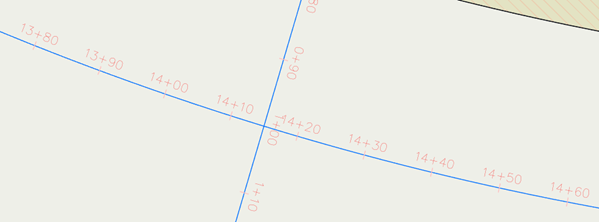
This example will show how to change the distance between the stations in the Alignment feature layer, from 10 meters to 15 meters. In addition, you will change the mask of the station, from having two digits (for example, 14+30) to three digits (for example, 1+430) after the plus sign.
This change can be made to the symbology of the AlignmentAlignment Profile, for either maps or scenes. In the following section, you will learn how to save changes that you make to an LYRX file to reuse and share your changes.
The symbology uses the m-value of these feature classes to position the stations along the alignment.
- From the Contents pane, browse to the Alignment feature layer and click Alignment to access to the symbology definition.

- Another way to do so is to right-click the Alignment feature layer and select Symbology.
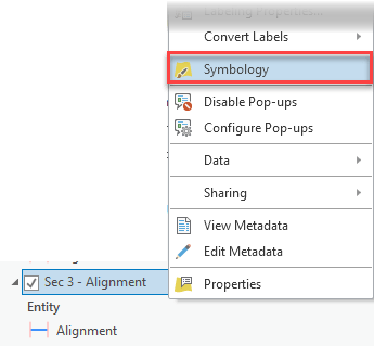
- Another way to do so is to right-click the Alignment feature layer and select Symbology.
- Once in the symbology definition, click the Alignment symbol.

- On the Properties tab, select the first definition.

- Scroll down, expand the Marker Placement group, and click the drum in the Interval option.

This will open a code editor from where you need to change a value.
- Select the X to open the editor.
 Arcade code initially checks whether the Type of the alignment is different than Offset and the Style is different than Offsets. These values are read from attributes in the feature class. If the alignment doesn’t have any of those values, apply a number for the interval, in this case, 10, and that is the value that you need to change.
Note:
In Autodesk Civil 3D, the default symbology for the alignments renders those with the Offset type without the station, and that is what you are doing here. If the alignment is Offset, it takes the default value of 0, which means no stations will be rendered.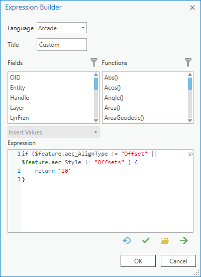
- Replace the value 10 with 15 and click OK to save the changes.

- Click OK in the Set Attribute Mapping section.

- Click Apply in the Symbology definition window.

The symbology is refreshed in the map, and you can see that the stations now are rendered every 15 meters.

- From the station definition (that was accessed in the previous section), expand the Appearance group and open the drop-down list for Element. Then select the last row, which is empty. This will give you access to the text definition.

- Click the drum for Text string.

- Select the X to open the editor.
- Expand and review the code.
There are functions used to build the mask for the $measure value. The generated mask looks like this: ###00+00.##
You’ll change the mask to make it look like this: ###0+000.##.
In line 4, add a 0 to the mask definition ## so it would look like 000.##.
In line 5, replace 100 with 1000. Then change the mask, removing a 0, so from ###00 so it would look like ###0.

Click OK to save the changes and close the editor.
- Click OK to save the changes and close the editor.

- Click OK in the Set Attribute Mapping section.
- Click Apply in the Symbology definition window.
The symbology is refreshed in the map, and you can see that the stations now are rendered with the new mask

- From the Contents pane, browse to the Alignment feature layer where you changed the symbology definition and right-click and select Sharing > Save As Layer File.
- Select a directory where you want to save the LYRX file and click Save.
Now that you have the symbology changes saved in a file, you can apply this symbology manually to a feature layer, or you can use this file to overwrite the default symbology definition of ArcGIS Pro for the corresponding Civil 3D entity type.
- Go to the symbology definition of the feature layer where you want to apply the symbology and select Import symbology.
The Apply Symbology From Layer geoprocessing tool opens.
- In the Symbology layer, select the LYRX file that you saved in a previous step, and click Run.
When the tool finishes running, the symbology will be updated in the map.
After performing changes to the symbology, they will apply only to the feature layer where you made them. You can make these changes available to be used for other alignments, and they can also become the new default symbology when new alignments are added to the map or other maps.
To do this, you need to save the feature layer definition as an LYRX file.
To apply the LYRX file as the new default symbology for a specific type of Civil 3D entity, you need to replace the out-of-the-box file with the new one in this folder.
C:\Program Files\ArcGIS\Pro\Resources\LayerTemplates\CAD\en-US. You need to follow the naming convention so the file will be taken by ArcGIS Pro the next time that it's needed. For example, you need to rename the file to CAD_Alignment.lyrx. It is a good practice to keep a copy of both the new and the original LYRX files. If you have customized one or more LYRX files, and later you uninstall ArcGIS Pro, the file with the custom symbology will be uninstalled. And the next time you install ArcGIS Pro, the default symbology will be used. So, you will need to apply your file to that directory again to apply your custom symbology.