Available with Standard or Advanced license.
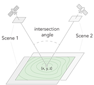
A digital terrain model (DTM) is a bare-earth digital elevation dataset, with above-ground objects—such as trees and buildings— filtered out. DTMs can be derived from stereo image pairs using photogrammetric methodologies. A stereo pair is composed of two overlapping images of the same geolocation taken from different perspectives. The stereo image pairs of an image collection are used to generate a point cloud (3D points) from which elevation data can be derived. Stereo image pairs are also used to support stereoscopic image analysis, 3D feature compilation, and mapping applications. Typical image overlap to produce point clouds is 80 percent forward overlap along a flight line, and 60 percent overlap between flight lines, so that every location on the ground is covered by multiple images.

The derived elevation data can be used in a various applications including orthorectification of the image collection in the Ortho mapping workspace. The recommended image type for generating a DTM is vertical imagery.
Generate a DTM
To generate a DTM using the Ortho mapping DTM wizard, follow the steps below.
Note:
- Before you begin the workflow, ensure that you have created an Ortho mapping workspace and completed the block adjustment process.
- DTM generation is recommended using nadir imagery.
- The minimum number of images required to generate a DTM product is two overlapping images. Product quality is increased with more overlapping images.
- On the Ortho Mapping tab, click the DTM button
 in the Product group.
The DTM Wizard window appears.
- Click Next.
- In the Point Cloud Settings window, for Matching Method, choose Semiglobal Matching (SGM) from the drop-down menu.
This method is typically used for images of urban areas and captures more detailed terrain information. If a quick result is required, choose Extended Terrain Matching (ETM), but this method does not provide the same detail as SGM. In regards to processing speed and product quality, the Multi-View Matching (MVM) method is in the middle of the three matching methods.
- Ensure that Filter Ground Objects is checked.
- For Maximum Object Size to Filter, use the default value of 10 meters.
Objects smaller than this threshold will be filtered as ground; otherwise objects will be treated as above-ground features, such as buildings, bridges, or trees.
- Ensure that Point Ground Spacing is blank.
This defines the spacing, in meters, at which the 3D points are generated. The default is 5 times the resolution of the source imagery.
- Accept all remaining default settings and click Next.
- For information about the Advanced Settings options, see Create elevation data using the Ortho mapping DEMs wizard.
- In the DTM Settings window, set an appropriate Cell Size value for the DTM.
The Cell Size default value is 5 x GSD.
- For Format, choose a value from the drop-down list.
- Optionally, choose a Compression value.
- Set an Interpolation Method value, such as Bilinear.
- Choose a Smoothing Method value from the drop-down list.
- For Mask Polygon Features, select a feature class to set the boundary and constrain the DTM product output.
- Accept the remaining default settings and click Finish.
The DTM, defined by the mask polygon, is created.

