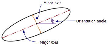
The Ellipse tool  creates planar ellipse features using the pointer or entered values. This tool is available in the Create Features pane with line and polygon feature templates.
When you use this tool, consider the following:
- Vertices for 3D z-aware features are assigned z-values based on your current elevation settings.
- The feature is automatically finished when the center location and major and minor axes are fully defined.
- The construction toolbar is not available with this tool.
Note:
If the active map is set to a geographic coordinate system, your specified distances and directions are measured using the North Azimuth (0 degrees) system and may produce unexpected alignment or accuracy errors.
To avoid these types of errors, the best practice is to assign the active map a projected coordinate system that matches the coordinate system of the layer or layers you are editing.
To create features that account for the earth's ellipsoid surface, use the Construct Geodetic tool  or consider using the Two-Point line tool
  with code-value domains to specify direction types in an attribute field named Azimuth Type.
Draw or enter numeric values
To draw an ellipse feature, complete the following steps:
- Add your data and configure settings for editing.
Confirm the feature layer you are editing is editable, the coordinate system assigned to the active map is suitable for the type of edits you're performing, and snapping is configured to help you work efficiently and accurately.
- On the ribbon, click the Edit tab. In the Features group, click Create
 .
. - In the Create Features pane, click a polyline or polygon feature template.
- Click the Ellipse tool
 .
.To override default attribute values or change optional tool settings, click the Active Template button
 and click the following tabs:
Attributes

Enter values in the attribute fields to override the source default values.
Ellipse

Check Modify existing polygons to prevent overlapping to automatically clip existing polygons on the same layer if they overlap your new feature.
- Click the map to create the center point.
To enter a coordinate location, right-click the map and click Absolute X,Y,Z
 .
. - Move the pointer and click the map to specify the orientation angle.
To enter a direction value, right-click the map and click Direction
 .
. - Move the pointer to specify the major and minor axes, and click the map.
To enter a coordinate location, right-click the map and click Absolute X,Y,Z
 .
.
To enter width or height values, right-click and click the corresponding command described in the following table.
Button Description Width

Enter the width value. If this value fully defines the feature, the feature is automatically finished.
Height

Enter the height value. If this value fully defines the feature, the feature is automatically finished.
Keyboard shortcuts
The keyboard shortcuts described in the following table provide an alternative way to execute commands for this tool.
| Keyboard shortcut | Action | Comment |
|---|---|---|
F6 | Specify absolute x,y,z | Open the Absolute X,Y,Z dialog box. |
A | Specify the direction | Open the Direction dialog box. |
Shift and drag | Make the geometry a circle | Constrain the geometry to a circle. Create the first point of the ellipse, press the keyboard shortcut, and drag. |
 .
.