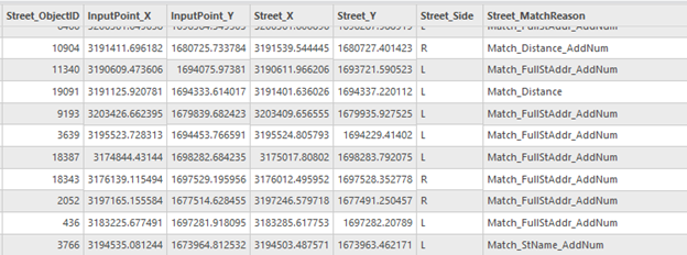
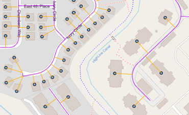
After running the Assign Streets To Points tool to link point addresses to street segments, the output point feature class contains a copy of the input point address data and the coordinates of the input point geometry in the InputPoint_X and InputPoint_Y fields and the coordinates of the point at the side of the linked street segment in the Street_X and Street_Y fields. These sets of coordinates can be used to create fishbone analysis lines illustrating the relationship between point addresses and the associated street segments to review the linked data. The point features with a value of Unmatched in the Match_Reason field have null geometry that will not display and cause warnings when generating the fishbone lines.

Generate fishbone lines
To generate the fishbone analysis lines from the point addresses to the linked street segments, complete the following steps:
- On the Analysis tab in the Geoprocessing group, click the Tools button
 .
.
The Geoprocessing pane appears.
- Select the XY To Line tool.
- In the Geoprocessing pane, click the Toolboxes tab.
- Click Data Management Tools in the list of geoprocessing toolboxes.
- Click Features in the list of toolsets.
- Click the XY To Line tool in the list of features tools.
- In the XY To Line tool, click Input Table and select the output result from the Assign Streets To Points tool.
- Modify the Output Feature Class parameter to rename the output data.
- Select InputPoint_X from the drop-down menu for the Start X Field parameter.
- Select InputPoint_Y from the drop-down menu for the Start Y Field parameter.
- Select Street_X from the drop-down menu for the End X Field parameter.
- Select Street_Y from the drop-down menu for the End Y Field parameter.
- Click the Line Type drop-down list and choose Planar line if the data is projected.
If the data is in a geographic coordinate system, use the default Geodesic option.
- Check the Preserve attributes parameter to include all of the attributes from the input.
- Click Run
 .
.Note:
Some tools will not work if the output feature class has features with no geometry, which is the case for point addresses that were not matched to a street segment. Select all features that contain geometry to exclude the features with no geometry before running the tool. Otherwise, resolve the records to a geometry in some other way, for example, by evaluating and creating a point manually or by rerunning the tool with unmatched records selected and increasing the Distance parameter in the Assign Streets To Points tool.
After generating the fishbone lines, use Select By Attributes  to select the Match_Distance_AddNum, Match_Distance, or Unmatched values in the Match_Reason field to review the point addresses that did not get linked to a street segment based on all of the street address components or only the street name component.