Доступно с лицензией Production Mapping.
The U.S. National Grid Reference Box is a layout element that references the Universal Transverse Mercator (UTM) grid zone designator and the two-letter location identifiers of the 100,000-meter grid squares that cover the extent of the active data frame. Multiple combinations of grid zone identifiers and 100,000-meter grid squares are possible when the data frame extent crosses zone boundaries.
Примечание:
The scale must be set to 1:250,000 or larger to use this tool.
Grid zone designations are unique identifiers specified with numbers from 1 to 60 for the UTM zones and letters C through X (skipping I and O) specifying 8 degrees of latitude each, starting at 80 degrees south and ending at 84 degrees north.
Each grid zone is subdivided into 100,000-meter grid squares specified by two-letter identifiers, with the first letter indicating a column and the second letter indicating a row.
The information displayed in the reference box, including the grid zone designation and the two-letter location identifiers of the 100,000-meter grid squares, is initially determined by the map extents.
Insert a U.S. National Grid Reference Box
The U.S. National Grid Reference Box can be inserted on any map layout with data located in the U.S.
- Ensure that a layout with a map frame is open and is the active view in your project.
- Click the Insert tab.
- Click the Additional Surrounds drop-down arrow and click U.S. National Grid Reference Box in the Topographic group.

- Click the layout where you want to insert the U.S. National Grid Reference Box element.
The U.S. National Grid Reference Box is added to the layout.
Примечание:
The default font for the element's text is Univers LT 45 and Univers LT 55. If the fonts are not installed, the default font for the element's text is Arial.
Modify the U.S. National Grid Reference Box
You can modify the properties and appearance of the U.S. National Grid Reference Box element using the options on the Meter Reference Guide contextual tab, as well as the Element pane.
- Ensure that the layout that contains the U.S. National Grid Reference Box element that you want to modify is open and is the active view in your project.
- Click the element in the Contents pane.
The Meter Reference Guide contextual tab appears. You can modify some of the element's properties on this tab.
- Double-click the element in the Contents pane to open the Element pane and update more element properties as necessary.
Подсказка:
You can also right-click the element on the layout or in the Contents pane and click Properties
 to open the Element pane.
 - In the Element pane, click the Options tab
 .
.- Provide a name for the element in the Name text box.
This name appears in the Contents pane and must be unique.
- Specify whether the element is visible by checking or unchecking the Visible check box.
The default is visible.
- Specify whether the element is locked so that changes cannot be made by checking or unchecking the Locked check box.
The default is unlocked.
- Specify whether the element appears at a fixed height and width according to the specifications of the map product by checking or unchecking the Draw to specification check box.
If the Draw to specification check box is checked, the element cannot be resized.
- Click the Map frame drop-down arrow to change the map frame associated with the element.
- Click the Type drop-down arrow to specify the type of cartographic product associated with the element.
The element's appearance changes depending on the cartographic product specified.
- Click the Color drop-down arrow to change the element's color.
- Optionally, expand Accessibility and provide a description of the element in the Alt Text text box that assistive technologies can read when a PDF is exported.
- Provide a name for the element in the Name text box.
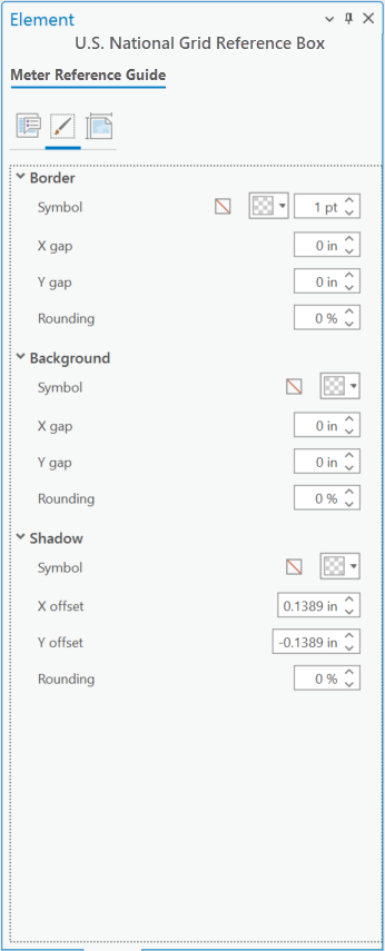
- In the Element pane, click the Display tab
 and configure display options as necessary.
- Configure the element's border in the Border section.
- Configure the element's background in the Background section.
- Configure the element's shadow in the Shadow section.

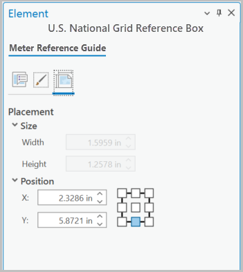
- In the Element pane, click the Placement tab
 and configure element placement options as necessary.
- Specify the element's size.
Resizing is unavailable if the Draw to specification check box on the Options tab
 is checked.
 - Specify the element's size and position.

These settings can also be set from the element's contextual tab in the Size & Position group.
- Specify the element's size.
The element is configured and modifications can continue to be made.