Note:
Nonspatial junction and edge objects are available with Utility Network Version 4 and later.
Junction and edge objects are nonspatial network objects used to model and work with a large number of real-world features that share a common geographical space, for example, the strands inside of a fiber cable or conductors in an underground duct. This allows organizations to model their network in more detail without the need to create features with shapes for every asset.
Junction and edge objects are unique among tables, in that they support connectivity with other features and can act as a container (such as a switch box that contains multiple ports). Associations are used to model connectivity, containment, and structural attachment between junction objects, edge objects, and other features in the network.
The structure and domain networks that comprise the utility network include two additional tables to model nonspatial objects.
- EdgeObject
- JunctionObject
- StructureEdgeObject
- StructureJunctionObject
One of the primary capabilities that expose the power of the utility network is the ability to model assets as they appear on the ground with a high degree of realism. Rows in both the JunctionObject and EdgeObject attribute tables participate in the network topology in the same way as spatial features to enable analytic capabilities such as tracing and diagrams.
In industries such as electric, gas, or water, junction and edge objects can be used to model underground structures such as the conduits, ducts, and inner ducts that represent the hierarchy of underground structures necessary to maintain cables and pipes. Asset modeling is not limited to simple representation of devices, cables, pipes, and so on; it also includes how they can be used for analysis.
Consider the example of telecom cables and the individual strands of fiber that exist in each cable. Telecom cables can contain thousands of fiber strands that transport data through the network. With assets such as these, it is necessary to model each individual strand, since each customer service may only use one or two. These nonspatial objects allow additional levels of granularity to be modeled effectively in this scenario. Representing thousands of fiber strands as spatial features could prove to be problematic, as you would have to work with stacked geometry, which would negate the value of spatial representation.
When modeling network features that contain multiple levels of granularity, such as in an underground electric or telecom network, you have to consider that large hierarchies of equipment exist at both the substation (for example, rack, device, slot, card, and port) and cable level (for example, cable, buffer tube, and strand). Only the highest-level asset in the hierarchy must be represented as a feature with a shape, while all the other assets can be represented in a tabular format as either a junction or edge object associated with the spatial feature. In the previously mentioned example, the telecom cable could be modeled as a line feature and serve as a container for the fiber strand content represented as edge objects. The line feature is used to display a spatial location for the fiber strands to the user.
Synthesize geometry for edge objects in a trace
While nonspatial objects allow you to work with a large number of features without the need to manage geometry, there are situations in which you may want access to an object's approximate geometry to better understand connectivity or to visualize the path of a trace.
Tip:
For simple visualization, creating a diagram can be useful. Nonspatial junction and edge objects are processed in the same manner as spatial features when building a diagram, which means that diagram junctions, edges, and containers in a network diagram can be used to visually represent nonspatial objects. To learn more, see Junction and edge objects in network diagrams.
For scenarios in which you want to visualize the path of a trace through edge objects, the aggregated geometry result type option on the Trace and Add Trace Configuration tools can be used with the Synthesize Geometries parameter to infer and create geometry for edge objects that are traversed as part of a trace.
The geometry for an edge object can be synthesized in two ways. When an edge object is content of a line, geometry is inferred from the spatial container. When an edge object has no spatial containment and this is not possible, geometry is synthesized between the endpoints of the edge object.
Note:
The Synthesize Geometries parameter requires ArcGIS Enterprise 11.3 or later when using an enterprise geodatabase.In the example below on the left, you can see junction and edge objects (in gray) contained by spatial point and line features (in blue) through a containment association (in orange). Looking at the image on the right, if you were to place a starting point on one of the junction objects and run the trace, geometry is synthesized and returned (in highlighted purple) in the aggregated geometry result. When geometry is inferred from an edge object's spatial container, the original container geometry is preserved.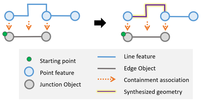
The examples below demonstrate scenarios in which the edge object (in gray) is not contained by a spatial feature. In example A, there is no line feature present. The endpoint junction objects (in gray) are instead content of the point features (in blue). When the trace is run, geometry is synthesized as a straight line between the endpoints as shown on the right (in highlighted purple). In cases in which an endpoint's container is nonspatial, locations are derived from the first spatial feature in the containment hierarchy. Example B outlines a similar scenario. Looking at the image on the left, you can see a line feature (in blue); however, it does not contain the edge object. In this case, on the right, when the trace is run, the line feature's original geometry is not preserved when synthesizing geometry (highlighted purple) because the edge object is not content. 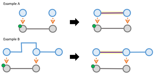
In scenarios in which an edge object is contained by more than one linear container, the unioned geometry of the containers is returned in the aggregated geometry result, as outlined below: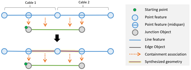
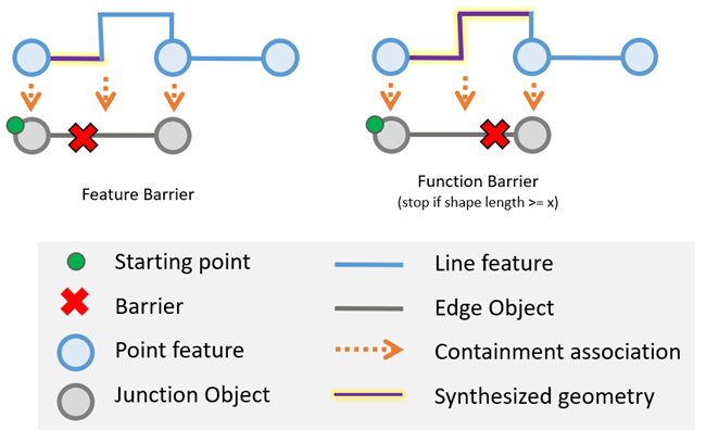
Because the Synthesize Geometries parameter is supported in conjunction with the Aggregated Geometry result type, the location of starting points and barriers placed midspan along an edge object can be used to return partial geometries when edge objects are content of a line feature. By default, trace locations are placed along edge objects with a percent along value of 0.5. This can be modified by editing the PERCENTALONG field for the starting point in the UN_Temp_Starting_Points and UN_Temp_Barriers feature classes.
The two scenarios below outline examples in which a barrier is present midspan along an edge object. The PERCENTALONG value is evaluated against the edge object's container geometry to return partial geometry in the aggregated geometry result. When an edge object is not content of a line feature, PERCENTALONG is ignored and the entire geometry between the endpoints is returned.
Locatability
Associations with spatial features are used to determine the location of, and visually represent, nonspatial objects on a map. For example, a port modeled as a nonspatial junction object can be associated with a switch device as content in a containment association. Nonspatial objects are added to the network topology when the network topology is enabled or through an association with a spatial feature in the association hierarchy during validation. If the association is deleted, or does not exist when the network topology is enabled, this can create a scenario in which the port is unlocatable.
The locatability of nonspatial objects is important because spatial features provide a mechanism to create dirty areas and validate edits made to nonspatial objects so they can be updated in the network topology. Junction and edge objects are locatable when they are contained by or structurally attached to a feature within their containment or attachment hierarchy.
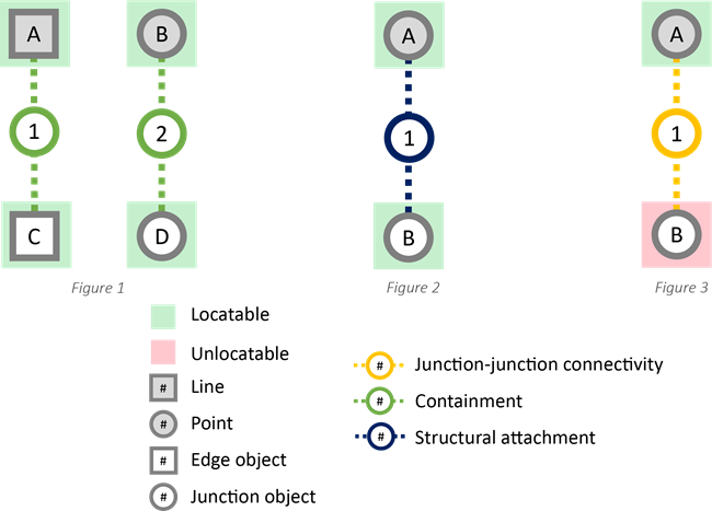
In figure 1 below, edge object C and junction object D are locatable through containment associations with spatial features, line A and point B, respectively. Similarly, in figure 2, junction object B is locatable through a structural attachment association with point feature A.
It is important to note that junction-junction connectivity associations cannot be used to determine the locatability of a junction object or edge object. Figure 3 shows that even though junction object B is associated with point feature A through a junction-junction connectivity association, it is considered unlocatable without another containment or structural attachment association to another feature or locatable object.
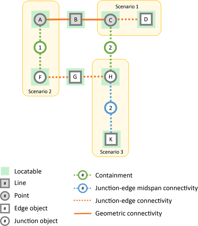
An edge object may also be located when associated with a junction at its endpoints or in situations in which the edge object is associated with a locatable junction object through a junction-edge or junction-edge midspan connectivity association.
For an example, see the scenarios below:
- In scenario 1, edge object D is locatable through a junction-edge connectivity association with point feature C.
- In scenario 2, edge object G is locatable through a junction-edge connectivity association with junction object F, which is locatable through containment association 1 with point feature A.
- In scenario 3, edge object K is locatable through a junction-edge midspan connectivity association with junction object H, which is locatable through containment association 2 with point feature C.
No dirty areas are created as a result of edits made to an object that is not locatable. As a result, these edits are not reflected in the network topology. Geometry and network attribute edits made to unlocatable objects require you to disable and enable the network topology to reflect the changes.
The Trace and Set Subnetwork Definition tools provide a Validate Locatability option to identify objects traversed during a trace that are not locatable through a containment, attachment, or connectivity association in their association hierarchy. When unlocatable objects are discovered, the tools return an error that includes the class name and global ID of the objects for inspection.
To learn more, see Ensure locatability of nonspatial objects.