Note:
For Utility Network Version 3 and earlier, see Error features.
Errors are generated by the system when a feature in a utility network is in violation of established rules and restrictions. When an error is discovered, a dirty area is created to encompass the feature's geometry. Errors can be corrected by making edits to the feature geometry, attribute values, network rules, or subnetwork definition. The next time the network topology is enabled or validated, the features with errors are evaluated.
Dirty areas that have associated errors will remain until the error situation is corrected. These could be resolved by making edits to the feature or by performing configuration changes to allow the error situation. Making configuration changes requires the network topology to be disabled.
For more information on error situations and solutions, see Error management.
What are errors?
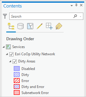
The dirty areas sublayer is used to manage errors in a utility network. The Contents pane is used to access this sublayer after adding a utility network to an active map view.
Attributes of the dirty area allow you to adjust the symbology and execute queries to highlight information on a map, for example, the feature class the error is associated with, or the type of error encountered. Information about the specific cause of the error can be identified using the symbology of the dirty area sublayer.
The dirty areas sublayer is symbolized using the Status field to indicate how it was created:

A dirty area is created for features with errors after enabling or validating the network topology. One or more errors can exist for a feature. These are represented by a single dirty area. The Modify Associations pane is used to display associations that are in error. Associations in error are displayed with an orange indicator next to the associated feature in the pane.
When are errors generated?
Errors are created when a topology is enabled or validated and when subnetworks are updated. Errors are created for a variety of reasons, from identifying empty geometries to discovering invalid asset types in a subnetwork. For a full list of error situations and solutions, see Error management.
Rules supporting connectivity are checked when the network topology is validated or enabled. Therefore, after a network topology has been validated or enabled, errors appear for any network features that violate feature restrictions or network rules.
Rules controlling associations are checked when you create or import an association, as well as when a network topology is enabled or validated. Errors are not created for associations when they are created or imported; instead, an error is returned in the tool or pane. Errors are created for associations when a network topology is enabled or validated.
Errors can be discovered during the initial configuration of a utility network. This is done for the purpose of discovering errors in your network to correct data before publishing. This process can be completed before registering the data as versioned, by using the Only generate errors option in the Enable network topology tool. See Enable a network topology for more information.
Examples of errors
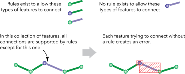
In the example below, a point feature has been placed geometrically coincident to a line feature. There is no rule to allow the two asset types to connect. When the network topology is validated or enabled, errors are generated. In this example, since no rule exists, an error is created for the point and line feature. In addition, the network features are not connected in the network topology.

Another example of a situation that violates restrictions of a utility network is coincident features that create ambiguity with regard to connectivity. These are cases where there are three or more coincident features and connectivity rules allow any of them to connected. For example, a dead end and a riser are located at the same endpoint on a medium-voltage line. There are two connectivity rules: one to allow the medium-voltage line to connect to the dead end and one for the line to connect to the riser. Since there are two possibilities, the utility network tracks this as an error. The utility network will not exhibit random behavior in terms of which feature is connected to which other feature. It will, however, tell you where you need to make that decision by flagging the features with errors.
In the example below, there are two types of network point features (riser and dead end) that do not allow geometric coincidence. Two additional errors will be created to track this violation for the point features.
