There are many core trace types provided with the Trace geoprocessing tool. Some traces rely on the tier definition for the domain network and also use the subnetwork definition, while others are not aware of the subnetwork properties for a utility network. Each trace type can be adjusted to refine the results by specifying additional configurations on the Trace tool. Review each trace type below to learn more.
Subnetwork-based traces rely on information from the underlying Domain Network and Tier parameters specified in the Trace tool to influence the trace results.
Each tier has a subnetwork definition that controls the properties or makeup of subnetworks participating in the tier. The subnetwork definition for the Tier parameter is used to preconfigure the trace with default settings. In addition, subnetwork-based traces are influenced by terminal configurations (valid paths and directionality). To learn more, see Connectivity and traversability.
Subnetwork-based traces that use the subnetwork definition in the trace configuration include the following:
Network traces that do not use the subnetwork definition in the trace configuration include the following:
To promote accurate trace results, ensure the network topology is valid for the areas of the network that will be traced. Trace results are not guaranteed to be accurate if dirty areas are present. Other than a visual inspection of the map, you can determine if dirty areas are present in your network by using the Validate Consistency configuration option on the Trace tool and checking the Dirty Area Count property in the network properties tab of the Layer Properties dialog box. Learn more about tracing utility networks and how to configure a trace.
The subnetwork-based traces identified above rely on subnetwork information. If a subnetwork is dirty, the trace will fail. To check if a subnetwork is dirty, inspect the Is dirty attribute in the Subnetworks table; true is dirty and false is clean. To clean a subnetwork, use the Update Subnetwork tool.
Note:
When working with an enterprise geodatabase, the Trace tool can only be used in a feature service environment.
Find connected features
A connected trace begins at one or more starting points and spans outward along connected features. A trace traveling along a path stops when either a barrier is encountered, or there are no more connected features (end of a path). This type of trace is useful for checking that newly edited features are connected as expected.
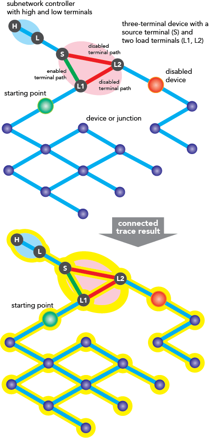
This type of trace travels the network based only on connectivity. It does not make use of a subnetwork definition, nor does it support terminal directionality or valid paths. Therefore, to control the traversability of this type of trace, configurations on the Trace tool must be configured manually. For example, instead of finding all connected features, you could locate all connected pad-mounted transformers (output asset type) over 35 kVA (output condition) and stop the trace when the sum of the transformer loads reaches 1,000 (function barrier). Using configurations during a trace to control how a trace travels a network is known as an advanced trace.
See Find connected features for more details.
Note:
Subnetwork controllers are not required for a Connected trace.
Trace a subnetwork
A subnetwork trace discovers all features participating in a subnetwork. Subnetwork traces require one or more starting points or a subnetwork name to determine what subnetwork to trace.
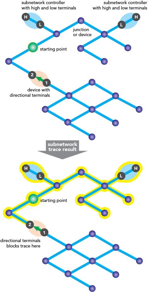
The trace begins at one or more starting points and spans outward along connected features to find subnetwork controllers that are traversable. Once a subnetwork controller is encountered, the trace spans outward from that controller along the subnetwork. A subnetwork trace stops when either a barrier or a feature that is not traversable is encountered, or when there are no more connected features. This trace type is useful for validating whether subnetworks, such as circuits or zones, are defined or edited appropriately.
Dive-in:
When the Subnetwork Name parameter is specified, the subnetwork controller or controllers for that subnetwork are used and any starting points set within the Trace Locations pane are ignored. The feature representing the subnetwork from the SubnetLine feature class is also returned in the trace results if no output filters are specified.
Although this type of trace uses the base subnetwork definition to autopopulate parameters, further configuration can be done using the Trace tool. For example, instead of tracing an entire subnetwork, adjust the trace to stop at valve features with a certain pressure using a condition barrier.
Subnetwork traces in hierarchical domain networks will traverse through controllers that have different tiers and only stop at controllers that have the same tier as the input tier. To stop traversal of a subnetwork trace based on tier groups, additional configuration is needed. A network category or network attribute can be created and assigned to boundary subnetwork controller devices for different tier groups, and these can be used within the trace configuration traversability section.
Subnetwork traces require a clean subnetwork; therefore, the traceable subnetworks must be updated if they are dirty. Terminals can impact a subnetwork trace by restricting flow. This includes only tracing through certain terminal paths based on the set of valid paths and traveling or not traveling through a terminal device based on directionality. To learn more, see Connectivity and traversability.
See Trace a subnetwork for more details.
Locate subnetwork controllers
A subnetwork controller trace is helpful to locate all subnetwork controllers for the traceable network. The trace begins at the starting point and spans outward to find the subnetwork controllers to return as the trace results; these are returned as a selection set.
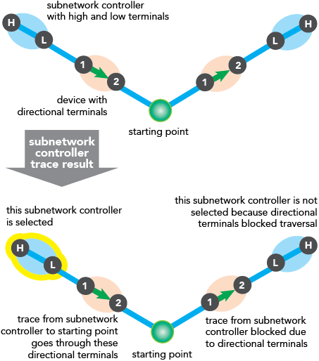
Subnetwork controllers associated with a subnetwork are those that have a path to the starting point and have the name of the subnetwork stored in the subnetwork name attribute. This can include boundary features such as tie switches in electrical networks. Tie switches bridge the boundary between two subnetworks.
Since this is a subnetwork-based trace, it uses the subnetwork definition and is influenced by terminals. To learn more, see Connectivity and traversability.
Locating subnetwork controllers requires a clean subnetwork. The traceable subnetwork must be updated if it is dirty.
See Locate subnetwork controllers for more details.
Find upstream or downstream features
The upstream or downstream direction of a subnetwork is determined on the fly during a trace. This is done by discovering whether the domain network is source or sink based and by locating the subnetwork controllers. Upstream traces travel toward subnetwork controllers in source-based domain networks and away from subnetwork controllers in sink-based domain networks. Downstream traces travel away from subnetwork controllers in source-based domain networks and toward subnetwork controllers in sink-based domain networks. Terminal configurations influence these trace types.
Note:
When loops are encountered during an upstream or downstream trace, trace results will return all features in a loop unless devices with a directional terminal configuration are present.
Both of these trace types require a clean subnetwork. The traceable subnetworks must be updated if they are dirty. Both types of traces travel the network based on traversability.
Downstream trace
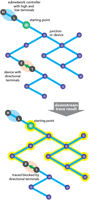
To perform a downstream trace, the subnetwork controller must be identified from the starting points to establish flow direction. Once identified, downstream traces travel away from the subnetwork controller (with flow direction) from the starting points in source-based networks and toward the subnetwork controller (with flow direction) in sink-based networks.
In both cases, if a barrier is encountered or there are no more connected or traversable features, the trace stops. Features between the starting points and downstream end locations are returned. If the starting point originates within a mesh, the entire mesh is included, as well as features downstream from the network protectors that delineate the mesh.
Upstream trace
To perform an upstream trace, the subnetwork controller must be identified from the starting points to establish flow direction. Once identified, upstream traces travel toward the subnetwork controller (against flow direction) from the starting points in source-based networks and away from the subnetwork controller (against flow direction) in sink-based networks.
If the starting point originates within a mesh, the entire mesh is included, as well as features upstream from the network protectors that delineate the mesh. When a barrier or the end of a path (either no more features, or where another subnetwork begins) is reached, the trace stops. Features between the starting point and the barriers or end of a path are returned in the results.
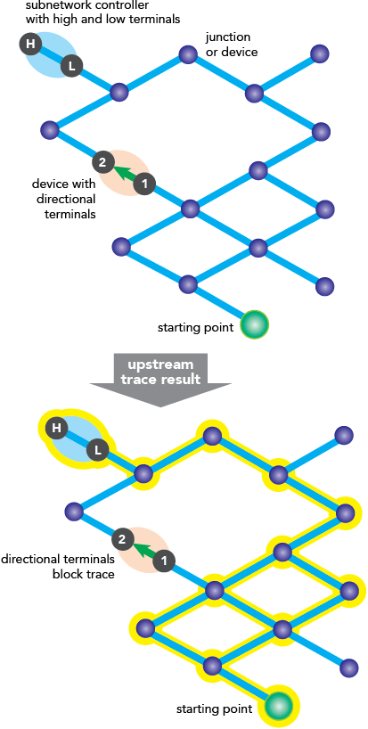
Configurations on the Trace tool can be used to modify an upstream or downstream trace. If you configure the trace to span multiple tiers, features from subnetworks in other tiers are returned (provided they are upstream or downstream). This is done by defining the Target Tier parameter for a trace.
An example of a modified upstream trace includes returning only upstream protective devices. A modified downstream trace example is a downstream trace spanning three levels executed on an electrical domain network with three tiers: distribution (Tier), subtransmission, and transmission (Target Tier).
See Find upstream and downstream features for more details.
Detect loops in your network
Loops are areas of the network where flow direction is ambiguous. Within a loop, resources can flow in either direction. Loops are expected with mesh networks but usually indicate error conditions in radial networks. You can discover loops using the Trace geoprocessing tool with the Loops trace type set.
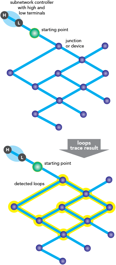
This trace begins at a single starting point and spans outward based on connectivity. Features participating in loops are returned as a single selection set. To augment the trace to travel the network based on traversability, parameters on the Trace tool can be set, making it an advanced loops trace. For example, configure the trace to detect loops in a set of electrical conductors for a certain phase.
See Discover network loops for more details.
Discover the shortest path
Identify the shortest path between two starting points using a trace. The shortest path is calculated using a numeric network attribute such as shape length. Cost- or distance-based paths can both be achieved using this type of trace.
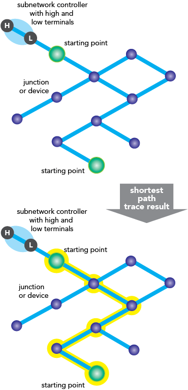
A shortest path trace does not use a subnetwork definition and does not require subnetwork controllers. This type of trace runs based on connectivity, with the exception of terminal paths. To incorporate traversability into this type of trace, parameters on the Trace tool can be explicitly set, making it an advanced shortest path trace. Advanced shortest path traces allow you to do such things as find the shortest path through 18-inch pipes between two points in a gas network.
The shortest path trace is subject to terminal paths, but not terminal directionality. When a terminal device is traced, the valid paths set for the device are respected. For example, a shortest path trace comes across a bypass switch in an electrical network. Valid paths for the bypass switch have been established, so the trace travels through the device along the valid paths; traces will not travel paths that are not valid. To learn more, see the Bypass switch example in Terminal management.
See Discover the shortest path for more details.
Locate isolating features
Note:
The Isolation trace type requires ArcGIS Enterprise 10.7 or later.
An isolation trace is used to determine the minimum set of operable features required to stop a network's resource, effectively isolating an area of the network. For instance, when a leak occurs on a water network, particular valves must be closed to eliminate water flow at the leak location. This prevents damage and allows field crews to safely start the repair process.
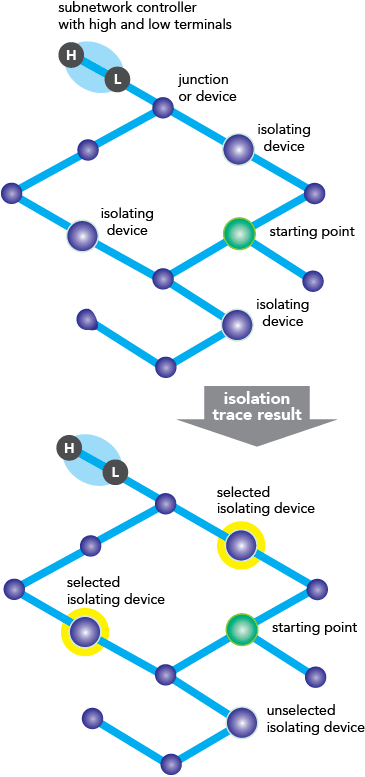
The Isolation trace type can find point and line features that isolate an area of a network. For example, in a gas network, pipes can be pinched to stop the flow of gas at the leak location.
As a subnetwork-based trace, the Isolation trace type uses the subnetwork definition set for the input tier. The trace begins at one or more starting points and spans outward along traversable features. The trace stops when either a barrier or a feature that is not traversable is encountered, or when there are no more connected features.
An isolation trace requires that a filter barrier be defined in the trace configuration to help pinpoint which features are isolating the starting point or points. This uses a specific network attribute or network category to stop the trace. For example, a filter barrier can be used with Category = Isolating. In this example, Isolating is a user-defined network category that is assigned to specific asset groups and asset types that are considered isolating. Additional filter barriers can be used to return valves with specific properties. For example, you can choose to return only accessible and operable valves: ones that are not paved over or rusted shut.
Note:
The Include Barrier Features check box is not available for isolation traces.
To include all of the isolated features in addition to the isolating barrier features, check the Include Isolated Features check box. For example, the valves or pipes that are isolating the leak location, plus all isolated features, will be returned. When checked, the trace results will include all features in the isolated area.
To refine the type of isolating features that are discovered during a trace, the Output section of the trace configuration can be used. For example, you can choose to return only bypass isolation valves.
See Locate isolating features for more details.