The Reduce Edge rule is used to simplify the diagram graph while preserving the topology by merging each expected network line feature or edge object and all its connection points into a schematic diagram junction. This type of junction is called a reduction junction.
Any reduction junction in the resulting diagram aggregates one network line feature or edge object and all its connection points; that is, a reduction junction cannot aggregate several network line features or several edge objects.
Reduce Edge rules process
The process operates on each network feature line or network edge object candidate for reduction. It detects all its connection points—both its extremity points and any points that are connected along that network feature line or network edge object—and aggregates all those features or objects under a specific reduction junction created during the rule process.
Connection changes and association reports when reducing edges
The following examples show how the Reduce Edge rule manages the graph and association reports in different situations:
Diagram A—Reduce Edge rule processing simple network line features or network edge objects
The first image below shows Diagram A before edge reduction, that is, the diagram content before the B1 black busbar simple line is reduced. This busbar is connected to the J1 and J2 junctions.
 |
The images below show Diagram A after edge reduction that preserves the reconnected edges (Result A1) or does not preserve them (Result A2).
 |  |
- In all cases, J1, J2, and B1 are no longer visible in the resulting diagrams, but the rule kept track of those features. They are now associated with a specific reduction junction, RJ1, created during the rule process—the black diamond junction.
- In the resulting diagram A1, the rule was set up to preserve the reconnected edges. This causes the E1, E2, and E3 edges that connected to the points along the busbar to be preserved and reconnected to the RJ1 reduction junction.
- In the resulting diagram A2, the rule was set up to aggregate the reconnected edges. This causes each E1, E2, and E3 edge that connected to the points along the busbar to be aggregated under a reduction edge, R1, R2, and R3. Note that each reduction edge keeps track of the real edges it aggregates.
Sample B—Reduce Edge rule processing network line features with midspan connectivity points
The first image below shows Diagram B before edge reduction, that is, the diagram content before the B1 black busbar line feature and all its midspan connectivity points are reduced—J1, J2, J3, and J4.
 |
The images below show Diagram B after edge reduction that preserves the reconnected edges (Result B1) or does not preserve them (Result B2):
 |  |
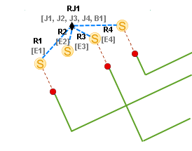
- Whatever the rule settings for the reconnected edges, J1, J2, J3, J4, and B1 are no longer visible in the diagram; they are now all aggregated under the reduction junction, RJ1 (the black diamond).
- When the rule is set up to preserve the reconnected edges (Result B1), any edges that connected to the midspan connectivity points along the busbar—that is, E1, E2, and E3—are preserved and reconnected to the RJ1 reduction junction.
- When the rule is set up to aggregate the reconnected edges (Result B2), each edge (E1, E2 and E3) is aggregated under a reduction edge (R1, R2, and R3), each one keeping track of the real edges it aggregates.
Edge reduction and containment
Regarding containment, the Reduce Edge rule processes the point that has the same status as the line to reduce, that is, Content or Not Content. If the line is a content feature or object, its related extremity points and connection points are fully reduced only if they all share the same container.
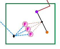
For example, in Diagram C below, there are two busbars, one with green connection and extremity points, and one with a black connection point and purple and orange extremity points.
 |
When all the points related to each busbar are contents, the Reduce Edge rule succeeds in fully reducing the two busbars. The resulting diagram looks like the one below:
 |
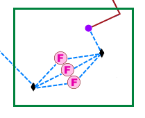
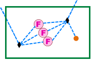
The examples below show situations in which the busbar at the right could not be fully reduced:
- Diagram C1 shows the result of the Reduce Edge rule when all the green points and their related busbar are content, but none of the black, orange, and purple points related to the second busbar are, or only the black one in the middle is.
- Diagram C2 is the result of the Reduce Edge rule when the purple extremity is not a content feature like the others.
- Diagram C3 shows how the Reduce Edge rule operates when the orange extremity is not a content feature like the others.
 |  |  |
Reduce Edge rule configuration
You can add a Reduce Edge rule to a template with the Add Reduce Edge By Attribute Rule tool.