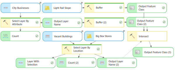
In ArcGIS Pro, you can use geoprocessing tools to perform spatial analysis and manage your GIS data. ModelBuilder is used to create, edit, and manage geoprocessing models that automate those tools. Models are workflows that string together sequences of geoprocessing tools, using the output of one tool as input to another tool. ModelBuilder can also be thought of as a visual programming language for building workflows.
To build a geoprocessing model in ModelBuilder, add tools and data to a model, and make connections between them to establish the run order.
Open ModelBuilder
On the Analysis tab, in the Geoprocessing group, click ModelBuilder to open it.
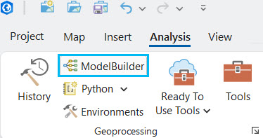
A new blank model is opened. The model is created in the project's default toolbox. You can resize, dock, or tile the model view in any position, as you would a map.
Add data
Models work with data, with the output of one geoprocessing tool used as input to another tool. You can start building a model by first adding the data you want to process.
To add data to a model, drag layers from the map Contents pane and datasets from the Project pane into the model.
The layers and datasets are added to the model and display as input data variables.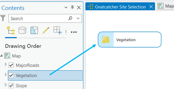
Add geoprocessing tools
Geoprocessing tools are a fundamental part of a model. ArcGIS Pro has many geoprocessing tools for accomplishing an extensive number of GIS tasks. Once you know the right tools for the work you are doing, it is straightforward to add those tools to a model.
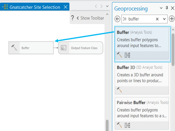
To add a geoprocessing tool to a model, ensure that the model view is active; then, start typing to search for a tool. A list of search results displays on the Add Tools To Model dialog box. Double-click a tool to add it to the model. Alternatively, you can drag a geoprocessing tool into the model from the Geoprocessing pane or Catalog pane.
The tool is added to the model and typically appears as a gray rectangle, indicating that the tool is not yet ready to run. In addition to the tool, any output data variables that will be created by the tool also appear in the model diagram.
Connect data and tools
Geoprocessing models allow connecting of data and tools into processes. You must specify which data variables in the model should be processed by which geoprocessing tools.
To connect the data variables you added to the model directly to a tool, draw a connection between them; then, choose the tool parameter to which to connect the variable. You can connect the output of one tool as input to another tool.
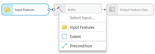
A connection line is drawn between the data variable and the tool.
Change tool parameters
Just as when you run a geoprocessing tool in the Geoprocessing pane, tools in ModelBuilder have required and optional parameters. Required parameters must be specified for the tool to run in a model.
To specify tool parameter values, double-click a geoprocessing tool in the model to open the tool and modify its parameters. After specifying all required parameters, click OK. The tool does not run when you click OK; it only saves the tool settings.
When all of a tool's required parameters have a valid value, the tool element color changes to yellow, indicating the tool is ready to run.
Set model parameters
You can make any variable into a model parameter. Variables that are set as model parameters show as tool parameters when the model is run as a geoprocessing tool, allowing you to specify different data or values for a model to process than what was specified when the model was created.
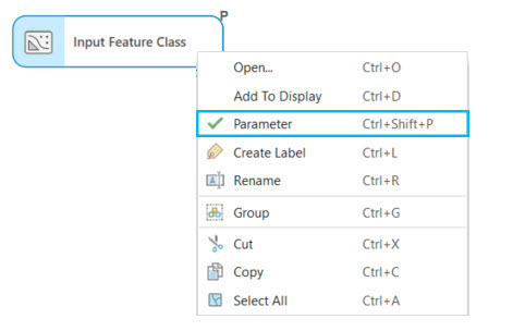
To set model parameters, right-click any variable in the model, and select Parameter to make the variable a model parameter.
An indicator (P) is displayed above the variable to indicate it is a model parameter, and a check mark appears next to the Parameter option in the variable context menu.
Run the model
Click the Run button  on the ModelBuilder tab to run the entire model.
While the tools in the model are running, a progress window appears that indicates which tool is running and any messages. As a model is running, the actively running tool is highlighted with a progress bar and a spinner.
A tool that is run successfully shows a green status bar and a Check Mark icon  , and a successful output shows a Check Mark icon
  . Any output variables that are marked Add To Display are added to the last active map.
