Smart Tree is a tree layout algorithm that applies to any type of diagram.
This layout algorithm arranges the diagram features hierarchically and places them in a smart tree according to the direction and spacing distances specified. By default, the tree branches are ordered according to their relative positions to each other that they have before the layout applies. Starting with ArcGIS Pro 3.6 and ArcGIS Enterprise 12.0, the tree branches can also be ordered according to attribute values on the branches; that is, according to an attribute existing on the lines or on the extremity junctions of the branches.
Root flags can be set up on diagram junctions before applying the Smart Tree layout.
When a root junction is specified in the diagram, the Smart Tree layout algorithm builds a smart tree starting from that junction.
When several root junctions are specified in the diagram, those root junctions are aligned along the same axis perpendicularly to the tree direction and appear as different start points for a tree branch of the diagram.
If no root junction is specified, the algorithm identifies the diagram junction associated with the smallest network topology index and uses this junction as the root junction.
The examples below show a diagram before and after applying the Smart Tree layout, respectively: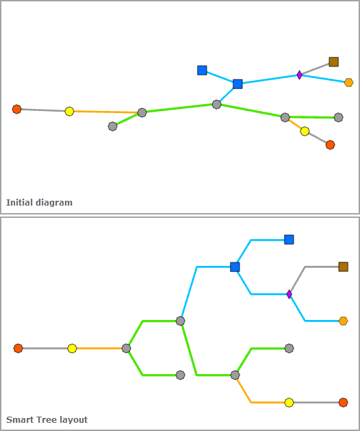
Apply the Smart Tree layout on an active diagram map view
When applying this layout on a network diagram, the following prerequisites must be met:
- Since this operation is transactional, edits must be saved before it is run.
- The input network diagram layer to which the layout applies must be from either a utility network or trace network in a file or mobile geodatabase, or a network diagram service. When working with a utility network or a trace network in an enterprise geodatabase, the input network diagram layer must be from a service.
To apply the Smart Tree layout on an active diagram map view, do one of the following:
- On the Network Diagram tab, click the drop-down arrow on the Diagram Layouts button in the Layout group, and depending on the tree direction you want, click one of the Smart Tree layout items in the gallery—
 ,
,  ,
,  ,
,  .
. - Load the Apply Smart Tree Layout tool in the Geoprocessing pane, adjust the Smart Tree layout parameters and click Run
Note:
To apply the layout algorithm on a subset of features in the network diagram, use one of the Select Features tools (for example, Select By Rectangle, Select By Polygon, and so on), and select the diagram features before running.
Configure the Smart Tree layout on a diagram template
To configure this layout on your diagram template, use the Add Smart Tree Layout tool.
Smart Tree layout parameters
The sections below clarify the main Smart Tree diagram layout parameters:

Preserve container layout
Most of the layout algorithms work with the Preserve container layout option. When this option is checked, it allows you to control the algorithm application so it runs on the top graph of the diagram. When this option is not checked, the algorithm is applied to both content and noncontent features in the diagram.
Tree Direction
This parameter sets the direction of the tree:
Spacing values interpreted as absolute units in the diagram coordinate system
Some layout algorithms work with the Spacing values interpreted as absolute units in the diagram coordinate system option. This option specifies how the layout algorithm parameters representing distances will be interpreted:
- Checked—The layout algorithm will interpret any distance values as linear units.
- Unchecked—The layout algorithm will interpret any distance values as relative units to an estimation of the average of the junction sizes in the current diagram extent. This is the default.
Between Subtrees
This parameter is used to specify the spacing between two neighboring subtrees, that is, the spacing between diagram junctions that are displayed perpendicular to the smart tree direction and belong to a different subtree, such as the A spacing below:
Between Junctions Perpendicular to the Direction
This parameter is used to set the spacing between diagram junctions that are displayed perpendicular to the smart tree direction and belong to the same subtree level, that is, the B spacing below: 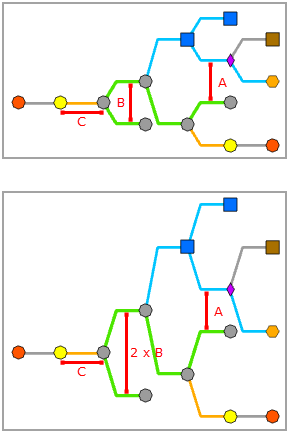
Between Junctions Along the Direction
This parameter value specifies the spacing between diagram junctions that are displayed along the smart tree direction, that is, the C spacing below: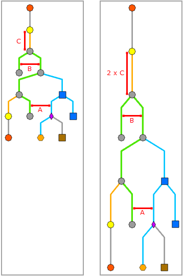
Between Disjoined Graphs
This parameter is used to specify the minimum spacing that must separate features belonging to disjoined graphs when the diagram contains such graphs, that is, the D spacing below: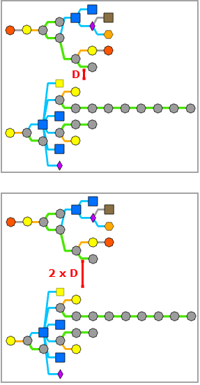
Edge Display Type, Break Point Relative Position, and Offset
These parameters are related. The Break Point Relative Position and Offset parameters are used depending on the specified Edge Display Type parameter value.
Edge Display Type
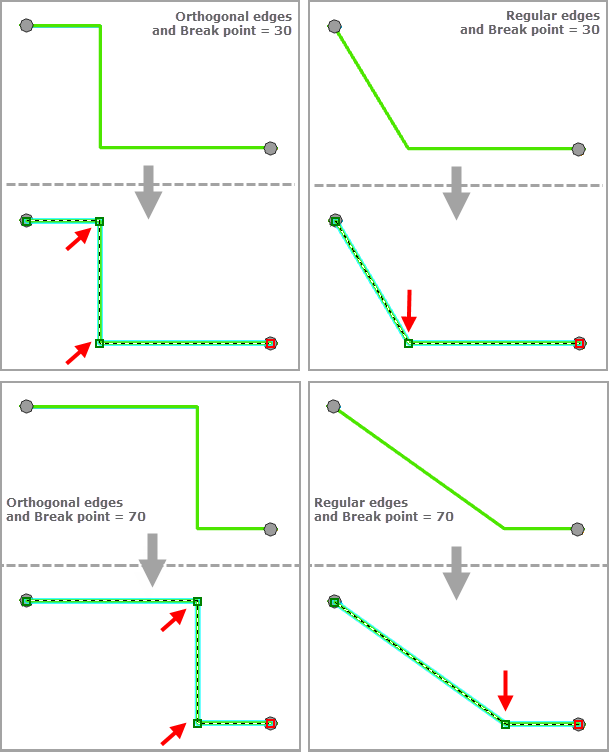
The Edge Display Type parameter specifies how diagram edges that are related to the tree branches display. There are three types of tree branch geometry:
- Curved edges—All diagram edges related to the tree branches are curved.
- Regular edges—All diagram edges related to the tree branches do not display with right angles.
- Orthogonal edges—All diagram edges related to the tree branches display with right angles.

Break Point Relative Position
The Break Point Relative Position parameter specifies the relative position of the break point that will be inserted along the diagram edges when Edge Display Type is Regular edges or Orthogonal edges. It is a percentage between 0 and 100.
- With a Break Point Relative Position (%) value of 0, the break point is positioned at the x-coordinate of the edge's from junction and at the y-coordinate of the edge's to junction for a horizontal tree. It is positioned at the y-coordinate of the edge's from junction and at the x-coordinate of the edge's to junction for a vertical tree.
- With a Break Point Relative Position (%) value of 100, there is no break point inserted on the diagram edges; each diagram edge directly connects its from and to junctions.
- With a Break Point Relative Position (%) value of N between 0 and 100, the break point is positioned at N% of the length of the [XY] segment, X being the x-coordinate of the edge's from junction and Y being the y-coordinate of the edge's to junction for a horizontal tree. It is positioned at N% of the length of the [YX] segment, Y being the y-coordinate of the edge's from junction and X being the x-coordinate of the edge's to junction for a vertical tree.
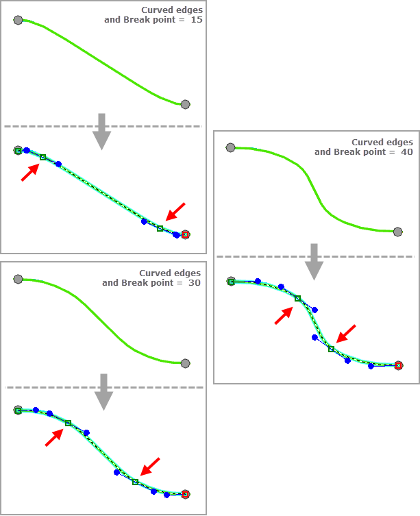
When Edge Display Type is Curved edges, the Break Point Relative Position parameter is used to compute the relative position of the two inflection points that will be inserted along the diagram edges to compute the curved edges geometry. It is a percentage between 15 and 40. With a Break Point Relative Position (%) value of N between 15 and 40, the following is true:
- X being the x-coordinate of the edge's from junction and Y being the y-coordinate of the edge's to junction for a horizontal tree:
- The first inflection point will be positioned at N% of the length of the [XY] segment.
- The second inflection point will be positioned at (100 - N)% of the length of the [XY] segment.
- Y being the y-coordinate of the edge's from junction and X being the x-coordinate of the edge's to junction for a vertical tree:
- The first inflection point will be positioned at N% of the length of the [YX] segment.
- The second inflection point will be positioned at (100 - N)% of the length of the [XY] segment.
Offset
When Edge Display Type is Orthogonal edges, the Offset parameter specifies the offset used to separate overlapping segments. It is a double value that cannot exceed 10 percent of the smallest value specified for the other spacing parameters.
Order tree branches according to an attribute, Attribute Availability, Attribute Name, and Attribute Sort Order
The Attribute Availability, Attribute Name, and Attribute Sort Order parameters are related and used when the Order tree branches according to an attribute option is checked.
The Order tree branches according to an attribute option specifies whether the tree branches must be ordered according to an attribute. When this option is checked, it allows you to order the tree branches according to an attribute. By default, this option is unchecked and tree branches are ordered regarding to the current positions of the branch extremity junctions at the moment the layout applies. For example, by default, considering the tree direction, any branch ending with junction A is placed above the branch ending with junction B when branch A already showed above branch B in the diagram before applying layout.
When the Order tree branches according to an attribute option is checked, the Attribute Availability, Attribute Name, and Attribute Sort Order parameters are used to order the tree branches.
Attribute Availability
The Attribute Availability parameter specifies if the attribute to consider is available on diagram junctions (Search the attribute on junctions; this is the default) or diagram edges (Search the attribute on edges).
Attribute Name
The Attribute Name parameter allows to specify the name or alias of the attribute field to use to order the tree branches when this field exists.
When you select Search the attribute on junctions in the Attribute Availability list, this order attribute will be queried on the branch extremity junctions.
When you select Search the attribute on edges in the Attribute Availability list, this order attribute will be queried on the branch extremity edges.
Attribute Sort Order
The Attribute Sort Order parameter allows to specify the sort order to consider for the tree branch positioning.
The sorting of the tree branches always applies from the first branch on the left to the last branch on the right for vertical tree layouts, and from the first branch at the top to the last branch at the bottom for horizontal tree layouts.
- When you select Ascending in the Attribute Sort Order list, the tree branches will be ordered regarding the attribute field values in their ascending order. This is the default.
For any horizontal tree layout, this makes the branch with the lowest attribute value to be placed at the top and the one with the highest attribute value at the bottom whether the tree structure is oriented from left to right or from right to left. Ascending for any vertical tree layout means that the branch with the lowest attribute value will be placed on the left and the one with the highest attribute value on the right, whether the tree structure is oriented from top to bottom or from bottom to top.

- When you select Descending in the Attribute Sort Order list, the tree branches will be ordered regarding the attribute field values in their descending order.
In this case, for any horizontal tree layout whether it is oriented from left to right or from right to left, this makes the branch with the highest attribute value to be placed at the top and the one with the lowest attribute value at the bottom. For any vertical tree layout, this means that the branch with the highest attribute value will be placed on the left and the one with the lowest attribute value on the right, whether the tree structure is oriented from top to bottom or from bottom to top.
