One common way to create spatial features is to draw them with editing tools. For example, you can trace objects on an image or construct shapes from a set of measurements.
When you create spatial features, you first create a feature class in which to store them. A feature class defines basic common properties of the features, such as their geometry type (point, line, or polygon), their coordinate system, their attributes (the categories of information they store), and whether they are 2D or 3D. Features that are 2D store horizontal x,y coordinates and are located on a flat surface. Features that are 3D also store a vertical z-coordinate, which gives them an elevation value in addition to a horizontal position.
Features are drawn, or constructed, with the help of a template. A template defines properties of features that can be set in advance, such as their map symbols, the editing tool used to create them, and sometimes their specific attribute values.
Overview
- This video was created with ArcGIS Pro 3.2.
In this tutorial, you'll create a feature class to store a set of 3D point features. You'll configure a feature template to define some properties of the new features in advance. Finally, you'll draw the features using an imagery basemap for reference.
- Estimated time: 30 minutes
- Software requirements: ArcGIS Pro Basic
Note:
The quick-start tutorials are updated at each software release. For the best experience, use an online help version that matches your software version.
Open the project
Your study area is Egmont National Park in the Taranaki region of New Zealand. You'll create 3D point features to represent road entrances to the park.
- Start ArcGIS Pro and sign in if necessary.
- Open a browse dialog box to search for the project in one of the following ways:
- On the start page, click Open another project
 .
. - In an open project, click the Project tab on the ribbon. In the list of side tabs, click Open. On the Open page, click Open another project
 .
.

- On the start page, click Open another project
- On the Open Project browse dialog box, in the navigation pane, under Portal
 , click ArcGIS Online
  .
.Note:
If you are signed in to ArcGIS Enterprise
 , you must set your active portal to ArcGIS Online to access the tutorial data. If you can't do this, you can download the data from a browser.
 - At the top of the dialog box, in the Search box, type Create points on a map and press the Enter key.
- In the list of search results, click Create points on a map to select the project package.
Note:
If there is more than one project package with this name, select the package with the Authoritative badge
 . In the Owner column, the owner name is ArcGISProTutorials. If you don't get any results, see No search results are returned.
 - Click OK.
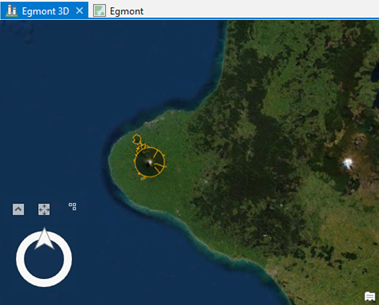
The project opens to the Taranaki region on New Zealand's North Island. The boundary of Egmont National Park is drawn with an orange outline. Mount Taranaki, an inactive volcano, is in the center of the park.
The active view is a local 3D scene named Egmont 3D. There is also a 2D map named Egmont.
- On the ribbon, click the View tab. In the Windows group, click Pane Sets
 and click Mapping
  .
.This ensures that the Contents and Catalog panes are open and that other panes are closed.
- Click the Map tab. In the Navigate group, click Bookmarks
 . Under Egmont 3D Bookmarks, click View from above to zoom to the park boundary.
 - Explore the scene with 3D navigation techniques and bookmarks.
With the Explore tool
 selected on the Map tab, you can navigate with the mouse. You can also use the on-screen navigator
  in Full Control mode.
Tip:
If you're not familiar with 3D navigation, see the help topics Navigation in 3D and Use the on-screen navigator or complete the Navigate maps and scenes tutorial.
- When you're finished, return to the View from above bookmark.
Create a feature class
You'll create a feature class in your project geodatabase to store the park entrance features. When you create a feature class, you specify its essential properties, such as its name, geometry type, and coordinate system. Optionally, you can add fields to the table and set advanced properties.
- In the Catalog pane, on the Project tab, expand Databases and expand create_points_on_a_map.gdb.
The project geodatabase already contains one feature class named ENP_Boundary. This feature class is the source data for the Egmont National Park layer on the map.
- Right-click create_points_on_a_map.gdb, point to New
 , and click Feature Class
  .
.The Create Feature Class pane appears. The pane contains six pages, but not every page needs to be completed.
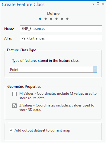
- On the Define page, for Name, type ENP_Entrances. For Alias, type Park Entrances.
In the feature class name, ENP stands for Egmont National Park. The alias is a user-friendly name that is given to map layers based on the feature class.
- For Feature Class Type, click the drop-down arrow and click Point.
Under Geometric Properties, the Z Values check box is checked by default. Point features added to this feature class will have z-values specifying their vertical position as well as x,y values specifying their horizontal position.
By default, the new feature class is added as a layer to the map, although it will not yet contain any features.
- At the bottom of the pane, click Next.
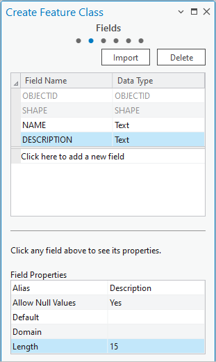
By default, a new feature class has only two fields: OBJECTID and SHAPE. You'll add fields for a feature name and description.
- On the Fields page, under the existing fields, click Click here to add a new field.
A new field is added. In the Field Name column, the default name is editable.
- Replace the default value with NAME. Press the Tab key to open the drop-down list of data types.
- In the Data Type list, click Text.
At the bottom of the pane, the properties of the new field are displayed.
- Under Field Properties, double-click the cell next to Alias to make it editable. Click the cell again and type Entrance Name. Press the Enter key.
- Double-click the cell next to Length and replace the default value with 35. Press the Enter key.

- Add another new field with the following properties:
- Field Name: DESCRIPTION
- Data Type: Text
- Alias: Description
- Length: 15
- Click Next.
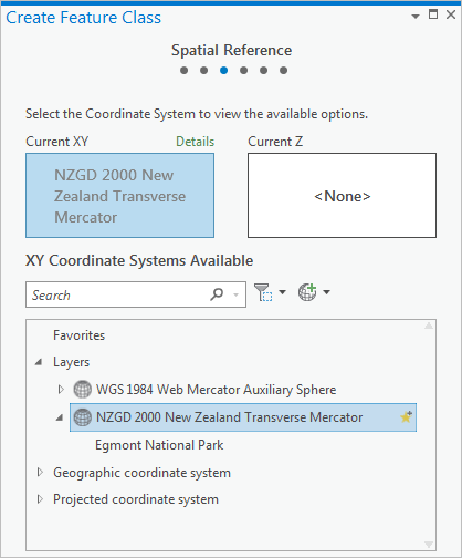
On the Spatial Reference page, you'll select a coordinate system. You'll use the New Zealand Transverse Mercator, a common standard in New Zealand. Because this coordinate system is used by the Egmont 3D scene, it appears by default in the Current XY box.
Note:
If you see a different coordinate system in the Current XY box, click NZGD 2000 New Zealand Transverse Mercator under Layers to set it as the Current XY system.
Learn more about specifying a coordinate system.
The remaining wizard pages can use the default settings. Learn more about setting spatial reference properties and storage configuration.
- Click Finish to create the feature class.
In the Catalog pane, the ENP_Entrances feature class is added to the default geodatabase. In the Contents pane, a layer based on the new feature class is added to the map with the following properties:
- Its name reflects the alias you assigned to the feature class.
- It appears under the 3D Layers heading because you created the feature class with z-values.
- Its visibility check box is dimmed because it doesn't have any features yet.
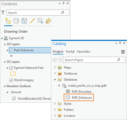
Before creating features, you'll symbolize the map layer and set feature creation rules with a feature template.
Symbolize the Park Entrances layer
You'll change the default symbol assigned to the Park Entrances layer.
- In the Contents pane, right-click the Park Entrances layer and click Symbology
 .
.The Symbology pane appears. The primary symbology is set to Single Symbol, which means that all features in the layer have the same symbol.
- Under the Primary symbology setting, next to Symbol, click the point symbol.

The pane shows options for formatting point symbols.
- Under Format Point Symbol, click the Gallery tab, if necessary.
- Next to the search box, click the All styles drop-down arrow and click Project styles.
The Project styles setting includes the styles ArcGIS Pro adds to the project by default, as well as any other styles you add. The All styles setting includes all system styles installed with ArcGIS Pro. Choosing Project styles narrows the scope of symbol searches.
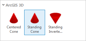
- In the search box, type cone and press the Enter key.
- In the list of available symbols, under ArcGIS 3D, click Standing Cone.
- Click the Properties tab. Click the Symbol tab
 under it, if necessary.
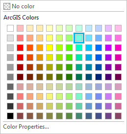
 - Under Appearance, click the Color drop-down arrow and click Beryl Green or another bright color.
- Change the symbol size to 8 pt and press the Enter key. Click Apply.
The symbol is updated in the Contents pane.
- On the Quick Access Toolbar, click Save Project
 .
.
Configure the feature template
Feature templates streamline data creation by specifying default properties for new features. These default properties include symbols, attribute values, and editing tools used in feature creation. Before configuring the feature template, you'll make Park Entrances the only editable layer in the scene.
- At the top of the Contents pane, click the List By Editing tab
 .
.Note:
An exclamation point
 next to a layer means that this type of layer is not editable.
 - Under 2D Layers, uncheck the Egmont National Park check box.
This layer can't be edited until the box is checked again.
Tip:
Alternatively, you can right-click the Park Entrances layer and click Make this the only editable layer
 .
. - At the top of the Contents pane, click the List By Drawing Order tab
 .
. - On the ribbon, click the Edit tab. In the Features group, click Create
 .
. The Create Features pane appears and displays the Park Entrances feature template.
- Under Park Entrances, click the Park Entrances template.

The Point tool
 is selected as the default editing tool for creating point features. On the map, the editing toolbar appears.
ArcGIS Pro is now in an active editing state—it is not necessary to take any further steps to begin creating features. However, before you add points to the map, you'll set default attribute values for the new features.
- On the feature template, click the Open the active template pane arrow
 to set default attribute values for new features.
Each feature will have a different name, so you won't set a default entrance name value. However, each feature will have the same description.
- Click the <Null> value next to Description and type Park Entrance. Press the Enter key.
Note:
The default Description value of Park Entrance is applied to new features as long as you edit the layer without interruption. It does not persist if you start editing a different layer or perform another software operation. To make default attribute values permanent in the feature template, right-click the template in the Create Features pane and click Properties
 . On the Template Properties dialog box, click the Attributes tab. Enter the attribute value you want and click OK.
Create a park entrance feature
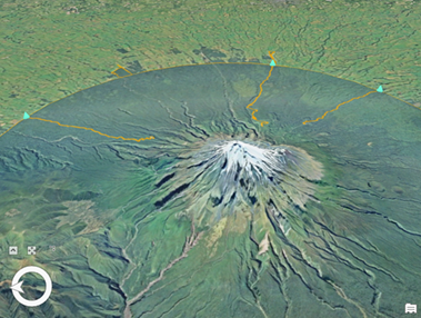
There are three road-based entries to the park. First, you'll create a point feature to represent the Egmont Road entrance.
- Confirm that the Egmont 3D scene
 is the active view. Hover over the scene.
The pointer changes to a crosshairs with a symbol attached to it. If you click in the scene, you'll create a point feature wherever you click.
Tip:
If you add a feature in the wrong place, click Undo
 on the Quick Access Toolbar.
 - On the ribbon, click the Map tab and click Bookmarks
 . Under Egmont Bookmarks, click Egmont Road.
The map zooms in to the road.
- Press and hold the C key on the keyboard.
The pointer changes to a hand pointer
 . As long as you hold the C key, you can pan the map without adding a point feature. You don't need to hold the C key to zoom in and out. Learn more about keyboard shortcuts for map navigation.
Tip:
You can also use the on-screen navigator
 to pan the map while an editing tool is active.
 - Navigate to the area where the road enters the park. To pan the map, click and drag the left mouse button while holding the C key. To zoom in and out, use the wheel button or hold the right mouse button and drag.
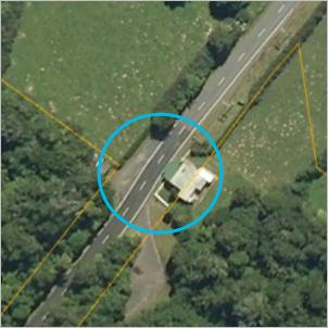
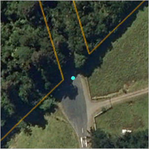
The park entrance is where the cleared land ends and the forest begins.
- Release the C key, if necessary. Click the road at the entrance to the park.
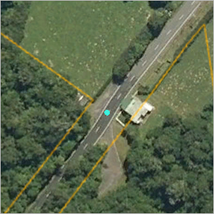
The feature is added to the map and is selected. You'll add an attribute value for the name of this entrance.
- On the ribbon, on the Map tab, in the Selection group, click Attributes
 .
.The Attributes pane appears.
- In the Attributes pane, click the <Null> value next to Entrance Name. Type Egmont Road and press the Enter key.
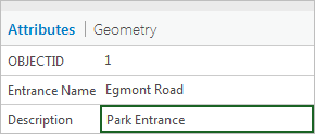
The description has already been added as specified by the feature template.
- Click Apply.
- Next to the Attributes tab, in the middle of the pane, click the Geometry tab.
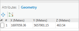
Along with the x- and y-values, a z-value is part of the point feature's geometry. The z-value should be close to 460 meters.
- Click the Attributes tab to show the feature's attributes again.
Create features for the other park entrances
You'll create features for the other two park entrances.
- On the Map tab, click Bookmarks
 . Under Egmont Bookmarks, click Pembroke Road.
 - Navigate to the area where the road enters the park.
- Click to add a point on the road.
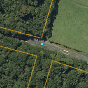
- In the Attributes pane, for Entrance Name, type Pembroke Road. Press the Enter key and click Apply.
- Go to the Manaia Road bookmark.
- Navigate to the park entrance and add a point.
- In the Attributes pane, for Entrance Name, type Manaia Road. Press the Enter key and click Apply.
- On the editing toolbar that appears near the bottom of the scene, click Finish
 .
. - On the ribbon, click the Edit tab. In the Manage Edits group, click Save
 .
. - On the Save Edits prompt, click Yes.
- On the Edit tab, in the Selection group, click Clear
 .
. - In the Contents pane, right-click the Park Entrances layer and click Attribute Table
 .
.
The table has three records with the attribute values you provided. The values in the Shape field are Point Z because the features have z-values.
- Close the table.
- Click the Map tab and click Bookmarks
 . Under Egmont 3D Bookmarks, click View from above.
 - On the Map tab, in the Navigate group, click Explore
 .
. - Navigate the scene and examine the park entrances from different perspectives.
View the layer in the map
Any layer can be displayed in either a 2D map or a 3D scene, regardless of whether the layer has z-values. You'll copy the Park Entrances layer from the 3D Egmont scene into the 2D Egmont map.
- In the Contents pane, under 3D Layers, right-click Park Entrances and click Copy
 .
. - Make the Egmont map view active.
- In the Contents pane, right-click the Egmont map name and click Paste
 .
.The Park Entrances layer appears at the top of the layers in the Contents pane and the features appear on the map.
- On the ribbon, click the Map tab and click Bookmarks
 . Under Egmont Bookmarks, click Egmont National Park.
 - Optionally, in the Contents pane, click the Park Entrances symbol. In the Symbology pane, click the Gallery tab and choose a different symbol.
- On the Quick Access Toolbar, click Save Project
 .
.
Add metadata
You'll add item description metadata to the feature class. An item description includes a title, tags, summary, and description. It may also include credits and use limitations. Metadata provides important background information about data. It is also indexed by ArcGIS Pro to generate search results when you search the project for data.
The steps in this section assume that you are using the ArcGIS Pro classic metadata editor and the Item Description metadata style.
Learn more about metadata styles and metadata editors
Note:
If you are using the ArcGIS Pro classic metadata editor with a different style, many additional metadata elements are present. Item Description is the only one you need to edit.
If you are using the ArcGIS metadata editor, the Item Description style is not available. Regardless of which style you use, the metadata elements that you need to complete the steps are available. However, the appearance, order, and validation of elements in your metadata view will be different.
- In the Catalog pane, right-click the ENP_Entrances feature class and click Edit Metadata
 .
.A metadata view opens. The elements of the metadata style are displayed in the Contents pane.
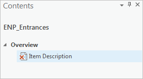
The metadata element is currently invalid
 because required information is missing.
 - In the metadata view, in the Title box, type Egmont National Park Entrances.
- In the Tags box, type (or copy and paste) the following keywords: parks, Egmont National Park, Taranaki, New Zealand.
Make sure the keywords are separated by commas.
- In the Summary (Purpose) box, add the following text: Identify road entry points to Egmont National Park.
- Click in the Description (Abstract) box.
In the Contents pane, the Item Description element is now marked valid
 because the required information (title, tags, and summary) is present.
Note:
If spell-checking is enabled in the Proofing options (as it is by default), unrecognized words are marked with wavy underlines.
- In the Description (Abstract) box, add the following text: Road entry points to Egmont National Park. The locations were identified with a park boundary layer and the Esri World Imagery basemap.
- On the ribbon, on the Metadata tab, in the Manage Metadata group, click Save
 .
. - Close the ENP_Entrances metadata view.
- In the Catalog pane, right-click the ENP_Entrances feature class and click View Metadata
 .
.A catalog view opens. In the details panel, the Metadata tab displays the metadata you added.

- On the Quick Access Toolbar, click Save Project
 .
.
To do more editing, try the Create points from a table and Author and share a local scene tutorials.
