Aviation Airports ライセンスで利用できます。
As features are created or edited you can modify the AirportSign layer's label properties to set the desired look for your airport signs.
Learn more about using labels in ArcGIS Pro
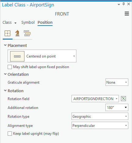
Rotation
Airport signs are rotated so that the front sign is facing the value from the AirportSign.AIRPORTSIGNDIRECTION field. This value is the bearing from true north that the sign faces. The back sign is rendered in the opposite direction of the front sign. If your data contains AIRPORTSIGNDIRECTION field values that don't fit this scenario, you can adjust for that by choosing a value from the Additional rotation or Rotation type option.
If you are working in a rotated map, an additional rotation would be needed on the labels. This can be done by adjusting the expression on the Rotation field to subtract the value of the map's rotation degrees. For example, if the map is rotated to 45 degrees, click the expression icon next to Rotation field and alter the expression to say:
$feature.AIRPORTSIGNDIRECTION + 180 - 45 for the FRONT label class,
$feature.AIRPORTSIGNDIRECTION - 45 for the BACK label class.
メモ:
You must use different values for the FRONT and BACK classes.
Reference scale
The graphic size and extent of the labels are determined by the map's reference scale. The reference scale is used when converting the labels to annotation for display on map products, such as an airport signage plan.
Arcade expressions
The appearance and content of the sign labels are determined by the label expressions that are used to process the AirportSign layer field values with font and color information. These Arcade expressions are provided in the ArcGIS Aviation Airports product files installer. You don't always need to modify these expressions, but they can be customized.
Modify layer expressions
The Arcade expression files provided in the Airports product data package provide a customizable label display for your airport signs.
You can find Arcade expressions for both the front and back labels of your airport signs under the \Arcade Expressions\Layers directory within the Airports product data package. These are already incorporated into the AirportSign_frontBack_layer.lyrx layer file. You can edit these expressions to fit your needs.
メモ:
You should only edit the layer expressions inside of the expression editor in the Label Class pane.
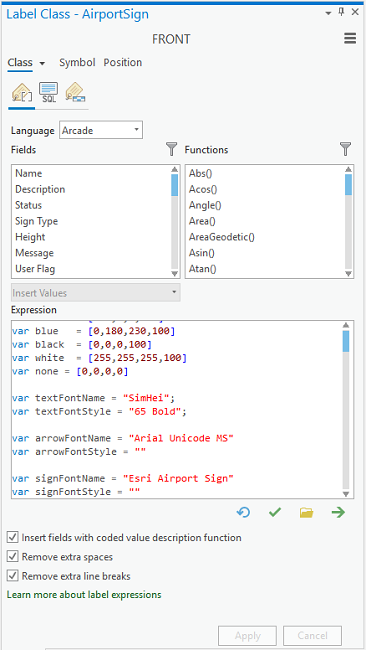
Learn more about writing Arcade expressions
Global variables
Global variable values can be set to change how your airport sign labels appear in ArcGIS Pro.
| Variable Name | Description | Data Type | ||||
|---|---|---|---|---|---|---|
| autoAdjustWidths | If set to true, this expression adds a filler on one side of the airport sign to match the opposite side's width. This value must be set to true for the labelAlignment and blackBackgroundFiller variables to work. | Boolean | ||||
| labelAlignment | Sets the alignment of text on the airport sign to right justified, or left justified.
| String | ||||
| blackBackgroundFiller | If set to true, this expression fills in the filler area on the airport sign with black. If set to false, the filler area is filled with the color on that side of the airport sign. | Boolean |
Offset Y
The front and back labels are positioned so that they are centered on, and offset from, the AirportSign point feature location. The Offset Y value sets how far from the feature the label renders. The values given for the FRONT section and the BACK section affect how far apart the front and back labels render from each other.
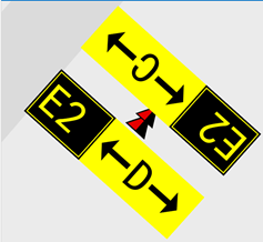
- On the Symbol tab, click the Position drop-down arrow.
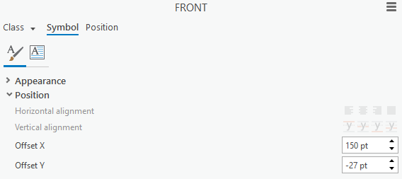
- Reduce the Offset Y value (for example, -27 pt) to show touching front and back signs.
You can configure the Maplex Label Engine settings to depict your airport signs differently. You can render signs over the sign location at a larger scale.
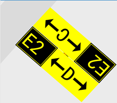
- [適用] をクリックします。
Offset X
You can use a smaller scale and use leader lines to point to a sign location with the labels placed for a best fit. You can edit the Offset X value—for example, 150 pt for the FRONTclass and -150 pt for the BACK class —and add the leader line symbol. This allows you to display larger signs at a smaller map scale and not obscure the sign's exact location on the map. Once these labels are converted to feature-linked annotation, they can be edited for a more precise placement.
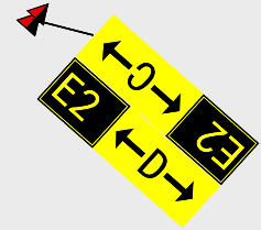
A leader line symbol can be added to either the FRONT or BACK class, but only one class is needed.
- On the Symbol tab, ensure that Background is chosen in the Callout drop-down menu.
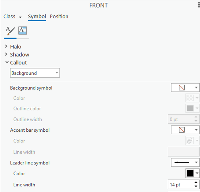
- Click the Leader line symbol drop-down arrow and choose a leader line symbol image.
- [適用] をクリックします。
Once the label preferences are set, the labels can be converted to feature-linked annotation.