There are two terms used to describe how utility network features relate to one another. Connectivity describes the state in which two features have geometric coincident-based connectivity or are connected via a connectivity association. Traversability describes the situation in which two features are connected or associated and have appropriate attributes. The attributes and attribute values considered during a trace are controlled by configurations set up through geoprocessing tools.
Application of tracing
A tracing operation travels a network in one of two methods, either by using connectivity or traversability.
Connectivity
Connectivity-based traces are those that rely only on the geometric coincidence and associations between features in your network. These types of traces have no concept of subnetwork definitions, terminal configurations, directionality, and so on.
The image below depicts a simple electrical source-based subnetwork. The square represents the subnetwork controller, the black lines are conductors, and the diamond is a network protector. The gray circles are assets that do not influence traversability but are still traceable. The portion to the left of the subnetwork controller is part of another subnetwork.

In a connected trace, the trace expands outward down all paths from a given starting point. Once the trace reaches the end of a path or a feature barrier, it stops there.

All features traced between the starting point and end locations are returned. The trace does not recognize the subnetwork as it goes beyond the controller; it does not recognize flow direction for a subnetwork, terminal directionality or paths, nor the network protector; a dynamic barrier specified in the subnetwork definition. Any features that are disconnected from the traceable portion of the network are not traced.
Traversability
Traversability is obtained when connected or associated features meet the requirements specified in a trace configuration.
The subnetwork definition for a tier indicates whether the subnetwork is a source-based or sink-based network. By default, this and the location of the subnetwork controllers are used to determine the directionality of the resource flow:
- Source-based subnetwork—The flow direction is away from the subnetwork controller.
- Sink-based subnetwork—The flow direction is toward the subnetwork controller.
For an upstream trace in a source-based network configure to stop at network protectors, there are a series of operations performed during the trace to discover traversability. When modeling flow using subnetwork controllers, flow direction is established by first locating the subnetwork controller. From the controller, the flow direction is determined for everything downstream. For this trace, this includes features that are connected to the nonupstream terminal. Once the flow is established, the upstream trace returns features that go against the flow. The trace stops at the network protector symbolized by the orange diamond.

Note:
The inclusion of barriers in a trace is optional.Alternatively, if you use a model that relies on the digitized direction of lines to determine the direction that resources flow in the network, the Use Digitized Direction parameter can be used with upstream and downstream traces to determine flow using the digitized direction of the line or the From and To global ID of the edge object in the association, and the Flow direction attribute. Regardless of the model you choose, the same traversability concepts apply.
Advanced configurations in the Set Subnetwork Definition and Trace tools allow you to control traversability settings. When advanced configurations are not set up or specified in the Set Subnetwork Definition or the Trace tools, the trace operation travels paths in the network based on connectivity. When advanced trace configurations are specified, the trace operation travels paths in the network based on traversability. Both connectivity and traversability are subject to barrier features.
Subnetwork information
A subnetwork is defined by a subnetwork controller and the subnetwork definition defined for the tier in which it participates. This includes the extent of the subnetwork, the direction of flow, and a definition for what features influence traversability. To learn more, see Subnetwork Management.
Connectivity-based traces have no concept of subnetwork controllers or subnetwork definitions. A connectivity-based trace begins at a defined starting point and travels the network in all directions until it reaches a feature barrier or there are no more features to trace.
Flow direction in traversability-based traces is influenced by the subnetwork controller and the Subnetwork Controller Type defined for the domain network. The Subnetwork Controller Type determines if subnetworks in a domain network are source-based or sink-based:
- In a source-based subnetwork, traversability-based traces travel away from the subnetwork controller.
- In a sink-based network, the trace travels toward the subnetwork controller.
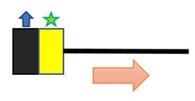
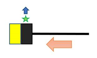
The following images illustrate flow direction in a source- and sink-based subnetwork:
- Black and yellow square—A device feature with multiple terminals
- Green star—Subnetwork controller
- Blue arrow—Upstream terminal


To learn more about terminals, see Terminal Management.
A ranking system is defined for tiers and tier groups when a network is configured. This ranking system allows the trace to travel the network in a logical sequence. For example, an upstream trace on a source-based network that spans five tiers starting on a subnetwork in tier three would travel up four and five but not down two and one. This is assuming the target tier has been set to five.
Aside from tier rank, a subnetwork definition can hold information that tells a traversability-based trace when to stop, what features to consider as barriers, what features to return in the results of a trace, how to manage and calculate attribute information on the fly, and so on.
To learn more about target tiers, ranks, and other subnetwork tracing properties, see Subnetwork trace configuration.
Application to terminals
Two properties defined for a terminal configuration influence traversability-based traces: directionality and valid paths. Directionality dictates which way a trace can travel through a feature. Directional confines a trace to only travel in one terminal and out the other. Bidirectional allows a trace to go in both and out both. Within a feature with terminals, there are paths between each and every terminal. To restrict what paths a trace can travel, valid paths are defined.
To learn more about terminals, see Terminal management.
Connectivity-based traces are not subject to the behavior associated with directional terminals nor the valid paths defined for a configuration. A device or junction object with terminals is treated as a single feature without terminals in a connectivity-based trace. Traversability-based traces are subject to both directionality and valid paths.
On a source-based network, once a Subnetwork, Subnetwork Controller, or Downstream trace travels in through the nonupstream terminal of a device or junction object and out through the upstream terminal, it cannot travel in through the upstream terminal, and out through the nonupstream terminal of another feature. The opposite goes for sink-based networks.
Subnetwork traces have an optional parameter on the Trace tool to allow a subnetwork name to be used instead of a starting point. When a subnetwork name is provided, instead of a starting point, the tool opens the Subnetworks table to look up all subnetwork controllers associated with a subnetwork. Thus, during a Subnetwork trace, the behavior mentioned above is only applicable to Subnetwork traces when a starting point is used, not when a subnetwork name is provided.
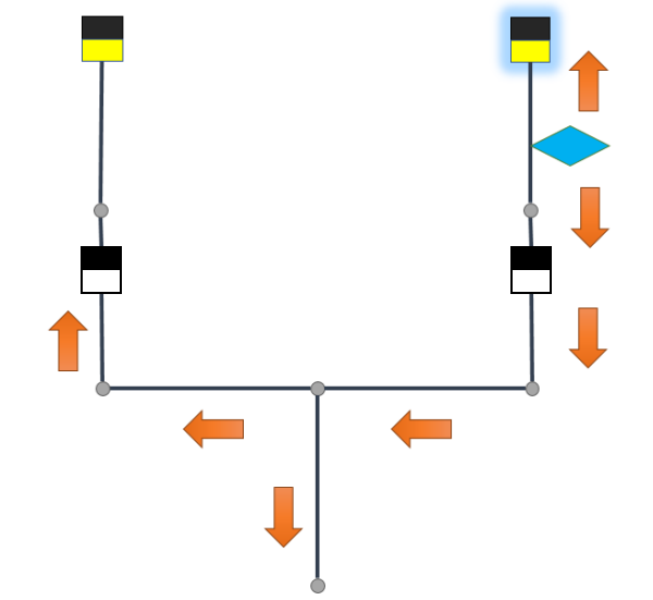
The image below represents a small source-based subnetwork:
- The squares represent features with
terminals.
- Yellow and black square—Subnetwork controller.
- Black represents the upstream terminal.
- White and black square—Two-terminal
directional device.
- Black represents the upstream terminal
- Yellow and black square—Subnetwork controller.
- The blue diamond and green triangle represent two starting point locations.

Scenario 1—A subnetwork controller trace starts from the blue diamond and spans outward north and south.

The trace returns the subnetwork controller on the right, highlighted in blue. The second directional device prevents the trace from finding the subnetwork controller on the left.
Scenario 2— A subnetwork controller trace starts from the green triangle. The trace spans north and then east and west to traverse the directional devices. Both of the subnetwork controllers are returned.
