The Traverse tool  supports efficient, single-handed entry using the numeric keypad. The sections below describe different traverse entry examples, shortcuts, and overrides.
Before entering a traverse, ensure that the distance and direction units have been set correctly for the project. You can also click the Direction and Arc Length field drop-down arrows on the traverse grid to configure default entry parameters for curved lines.
Learn more about creating traverses
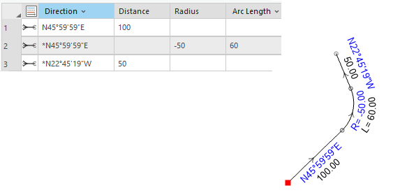
Traverse with curve to the left (quadrant bearing, feet)
The data is as follows:
- Straight line, N45°59'59'"E, 100.00 feet
- Tangent curve left, radius 50 feet, arc length 60 feet
- Exit curve tangent, straight line, 50 feet
In the traverse grid, the default curve parameters are set to Tangent for the Direction field and Arc Length for the curve parameter field.
To enter a traverse with a curve turning left, the keystrokes on the numeric keypad are as follows:
- 45.5959-1 ENTER 100 ENTER
- ENTER 0 ENTER -50 ENTER 60 ENTER
- ENTER 50 ENTER
Tip:
The * preceding the direction value in the Direction field indicates the direction is tangent to the previous line.
With the default curve parameters set to Chord for the Direction field and Arc Length for the curve parameter field, the same traverse would be entered as follows:
- 45.5959-1 ENTER 100 ENTER
- * ENTER 0 ENTER -50 ENTER 60 ENTER (The * indicates the direction should be tangent to the previous direction or tangent to the exit of a curve. In this case, the * indicates that the curve should be tangent, even though the default curve direction is set to Chord.)
- * ENTER 50 ENTER

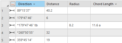
Traverse with curve to the right (north azimuth, meters)
The data is as follows:
- 89°15'37'", 40.2 meters
- 179°47'46'", 6 meters
- Tangent curve right, radius 8.2 meters, arc length 11.6 meters
- Exit curve tangent, straight line, 32 meters
- 359°45'14'", 19 meters, close traverse
In the traverse grid, the default curve parameters are set to Tangent for the Direction field and Arc Length for the curve parameter field.
To enter a traverse using north azimuth, meters, and a curve turning right, the keystrokes on the numeric keypad are as follows:
- 89.1537 ENTER 40.2 ENTER
- 179.4746 ENTER 6 ENTER
- ENTER 0 ENTER 8.2 ENTER 11.6 ENTER
- ENTER 32 ENTER
- 359.4514 ENTER 19* ENTER (The * in the Distance field indicates that the traverse should close onto its start point regardless of the specified closure tolerance).

With the default curve parameters set to Chord for the Direction field and Chord Length for the curve parameter field, the same traverse would be entered as follows:
- 89.1537 ENTER 40.2 ENTER
- 179.4746 ENTER 6 ENTER
- * ENTER 0 ENTER 8.2 ENTER 11.6a ENTER(* is the tangent direction override and a is the arc length override)
- * ENTER 32 ENTER
- 359.4514 ENTER 19* ENTER
Traverse starting with a nontangent curve (quadrant bearing, feet)
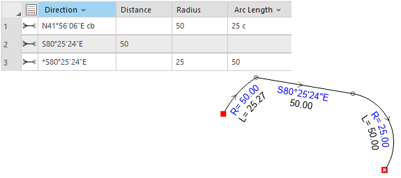
The following example shows overriding curve parameters in a traverse. The data is as follows:
- Nontangent curve with chord bearing N41°56'06'"E, radius 50 feet, chord length 25 feet
- Straight line, S80°25'24'"E, 50 feet
- Tangent curve turning right, radius 25 feet, arc length 50 feet
In the traverse grid, the default curve parameters are set to Tangent for the Direction field and Arc Length for the curve parameter field.
To enter a traverse starting with a nontangent curve turning right, the keystrokes on the numeric keypad are as follows:
- 41-56-06-1cb (or 41.5606-1cb) ENTER 0 ENTER 50 ENTER 25c ENTER(cb is the chord bearing override and c is the chord length override).
- 80.2524-2 ENTER 50 ENTER
- ENTER 0 ENTER 25 ENTER 50 ENTER
With the default curve parameters set to Chord for the curve direction field and Arc Length for the curve parameter field, the same traverse would be entered as follows:
- 41-56-06-1 (or 41.5606-1) ENTER 0 ENTER 50 ENTER 25c ENTER
- 80.2524-2 ENTER 50 ENTER
- * ENTER 0 ENTER 25 ENTER 50 ENTER (The * indicates the direction should be tangent to the previous direction or tangent to the exit of a curve.)

See the Curve overrides section below for more information on curve overrides.
Traverse with radial bearing curve (quadrant bearing, feet)
The following example shows entering radial bearing curves. The data is as follows:
- Straight line, S80°25'24'"E, 50 feet
- Straight line, 20° clockwise from previous bearing, 45 feet
- Curve with radial bearing, S41°26'06'"E turning right, radius 25, delta (central angle) 45
- Tangent curve turning right, radius 25, delta 45
- Straight line, N25°35'05'"E, 45 feet
- Straight line, 80° counterclockwise from previous bearing, 45 feet
In the traverse grid, the default curve parameters are set to Radial for the Direction field and Arc Length for the curve parameter field.
To enter a traverse with shortcuts, the keystrokes on the numeric keypad are as follows:
- 80.2524-2 ENTER 50 ENTER
- +20 ENTER 45 ENTER
- 41.2606-2 ENTER 0 ENTER 25 ENTER 45d ENTER (is the delta angle override)
- * ENTER 0 ENTER 25 ENTER 45d ENTER(* is the tangent direction override)
- 25.3505-1 ENTER 45 ENTER
- -80 ENTER 45 ENTER

Traverse with a curve that has a missing radius
If you need to enter a curve that has a missing radius, you can use the Circular Arc tool to compute the missing radius:
- Click the 2-Point Line tool
 below the traverse leg to activate the tool and the editing construction tools.
 - Right-click in the map and click Circular Arc
 to open the Circular Arc dialog box.
 - Click the drop-down boxes in the left column to choose the curve parameters and enter the corresponding curve values in the text boxes on the right.
For example, to enter a tangent curve with a delta and an arc length (radius missing), choose Tangent Direction, Delta Angle, and Arc Length as the curve parameters.
- After typing the last curve parameter, press the Enter key to create the curve and populate curve values in the traverse grid.
The radius is computed from the provided curve parameters and populated in the Radius field in the traverse grid.
Traverse with calculator shortcut (quadrant bearing, feet)
The following example shows a traverse that uses a calculator shortcut to add two values. In the Distance, Radius and Arc Length fields, you can add, subtract, multiply, and divide values. The data is as follows:
- Straight line, N45°25'30"E, 100.00 feet
- Tangent curve right, radius = 45 + half road width, arc length 60 feet
- Exit curve tangent, straight line, 50 feet
In the traverse grid, the default curve parameters are set to Tangent for the Direction field and Arc Length for the curve parameter field.
To enter a traverse with a calculator shortcut, the keystrokes on the numeric keypad are as follows:
- 45-25-30-1 ENTER 100 ENTER
- ENTER 0 ENTER 45+30 ENTER 60 ENTER
- ENTER 50 ENTER

Traverse with internal angles (north azimuth, meters)
In the traverse grid, internal angles are entered starting with a + or a -. The + indicates an angle going clockwise from the previous line and the - indicates an angle going anti-clockwise from the previous line. Before entering a traverse with internal angles, ensure that Backsight is set for the angle mode. To set the angle mode, click the traverse menu  and click Options.
A traverse with internal angles must start with a line with a known bearing or direction. This first line then becomes the backsight line for the first, entered internal angle.
The following example shows a traverse that is entered with internal angles instead of bearings:
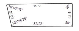
- Starting with the leftmost line, straight line going 90 degrees south, for 9.75 meters
- Straight line going 90 degrees west, for 32.22 meters from the previous line
- Straight line going at an angle 103°06'25", for 10.01 meters from the previous line
- Straight line going at an internal angle of 76°53'35 " for 34.50 meters from the previous line
To enter the above traverse with internal angels, the keystrokes on the numeric keypad are as follows:
- 180 ENTER 9.75 ENTER
- -90 ENTER 32.22 ENTER
- -103-06-25 ENTER 10.02 ENTER
- -76-53-35 ENTER 34.5 ENTER
Enter curves with internal angles
Tangent curves are entered the same way as you would enter them using directions. The direction of the previous line is used as the tangent direction for the curve. When entering a line or a curve following a tangent curve using internal angles, the exit tangent direction of the curve is used as the backsight line for the next internal angle.
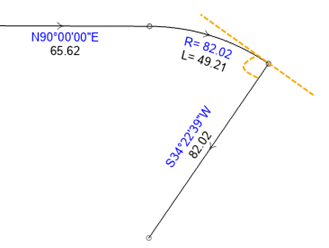
Chord bearing curves are entered using the internal angle between the previous backsight line and the chord line of the curve (orange angle in the graphic below). When entering a line or a curve following a chord bearing curve using internal angles, the exit tangent direction of the curve is used as the backsight line for the next internal angle (green angle in the graphic below).

Radial bearing curves are entered using the internal angle between the previous backsight line and the radial bearing of the curve (orange angle in the graphic below. When entering a line or a curve following a radial bearing curve using an internal angle, the radial bearing of the curve is used as the backsight line for the next internal angle (green angle in the graphic below).

Tip:
To view the radial bearing of a curve, enter an internal angle of +0. The next line drawn will be the radial bearing line of the curve.
Configure data entry parameters for curved lines
When entering curves in the traverse grid, the curve direction type can be set to tangent direction, chord direction, or radial direction. For new projects, the default direction type for the traverse grid is set to tangent direction. To change the default curve direction type, click the Direction drop-down arrow and choose Chord or Radial. To change the default curve parameters, click the Arc Length drop-down arrow and choose Chord Length or Delta Angle.
Curve parameters in the traverse grid can be temporarily changed with overrides at any time. For example, to override tangent direction with the radial direction, type rb after entering your curve direction, such as 41-56-06rb.
For the curve direction, type a negative radius for a curve turning left. Otherwise, the curve turns right.
For more curve overrides, see the Curve overrides section below.
Tangency
A traverse line or curve can be made tangent to the previous line or curve by typing an asterisk (*) in the Direction field and pressing Enter. After Enter is pressed, the Direction field is updated to display the tangent direction. An asterisk is placed before the direction value to indicate that it is tangent to the direction of the previous line.

If a direction value in the Direction field is preceded with an asterisk, it will remain tangent to the previous direction. This means that if the previous direction value is changed, the direction with the asterisk will be recalculated to be tangent to the updated value.
Additional keypad information
Keep the following in mind when working with the numeric keypad:
- Quadrant bearing is entered by typing a hyphen (-) and the number of the quadrant. For example, S80°25'24'"E can entered as 80-25-24-2 or 80.2524-2.
- The next course of the traverse is automatically populated with the exit tangent bearing of the previous course.
This makes it more straightforward to enter a tangent curve and exit a curve with a tangent straight line.
- To enter a circular curve, type a zero (0) in the Distance field and press Enter.
- A negative radius is used for a curve turning left. Otherwise, the curve turns right.
- An asterisk (*) in the Direction field indicates the direction should be tangent to the previous direction or tangent to the exit of a curve.
- An asterisk (*) in the Distance or Arc Length fields indicates that this is the last leg of the traverse and that the traverse should close regardless of the specified closure tolerance.
- Insert a row by right-clicking an existing row and clicking Insert Before or Insert After.
- Delete a row by right-clicking the row and clicking Delete Row.
- Reorder a row by dragging the row to a different location. The traverse is recomputed based on the new order of the courses.
- Reverse the direction of a course by right-clicking the course and clicking Reverse Direction.
- Move between cells in the traverse grid using the arrow keys or by pressing Esc.
Ground to grid
When Ground to Grid  is turned on, lines created from entered traverse dimensions are scaled and rotated by the specified ground to grid corrections. The entered dimensions are not changed.
To learn more, see Turn ground to grid corrections on.
Data entry shortcuts
The Traverse tool  uses the following shortcuts and overrides.
Quadrant bearing shortcuts
When entering directions using the quadrant bearing format, you can use numbers to specify the quadrant instead of typing the required letters. This allows you to work solely with the numeric keypad and speeds up the data entry process.
| Quadrant | Keystroke | Use in grid field | Example |
|---|---|---|---|
Northeast quadrant (NE) | -1 | Direction | 45-59-59-1 |
Southeast quadrant (SE) | -2 | Direction | 45-59-59-2 |
Southwest quadrant (SW) | -3 | Direction | 45-59-59-3 |
Northwest quadrant (NW) | -4 | Direction | 45-59-59-4 |
Closure shortcuts
Close a traverse using the following keystrokes:
| Keystroke | Use in grid field | Description | Example |
|---|---|---|---|
* | Distance, Radius, Arc Length, and Chord Length | Close a traverse onto its start point or defined closing location regardless of the closure tolerance. Closure is enforced. | 45-20-30-1 ENTER 25* |
Angle shortcuts
Direction calculation shortcuts can be used after the first traverse leg has been entered. The following direction calculation shortcuts use the direction in the previous traverse leg:
| Keystroke | Use in grid field | Description | Example |
|---|---|---|---|
+<angle> | Direction | Add the entered angle (clockwise) to the previous direction to get a direction for the next course. | +20 |
-<angle> | Direction | Subtract the entered angle (counterclockwise) from the previous direction to get a direction for the next course. | -20 |
+ | Direction | Add 90° (clockwise) to the previous direction to get a direction for the next course. | Type + instead of a dimension. |
- | Direction | Subtract 90° (counterclockwise) from the previous direction to get a direction for the next course. | Type - instead of a dimension. |
Calculator shortcuts
Use operators in the Distance, Radius, Arc Length, and Chord Length fields to quickly calculate and derive distances.
| Operator | Use in grid field | Description | Example |
|---|---|---|---|
+ | Distance, Radius, Arc Length, and Chord Length | Add two distances. | Add a ROW width to an existing radius to get the outer radius. Type 30+15 in the Radius field. |
- | Distance, Radius, Arc Length, and Chord Length | Subtract two distances. | Subtract a length described on a plan, for example, if the plan says, "..except the northern 52.8 feet," type 100-52.8 in the Distance field. |
* | Distance, Radius, Arc Length, and Chord Length | Multiply a distance. | Enter a road frontage and multiply the value by the number of lots with the same frontage to get the length of the ROW frontage. Type 40*4 in the Distance field. |
/ | Distance, Radius, Arc Length, and Chord Length | Divide a distance. | Divide a line to get the proportioned width. Type 122/3 in the Distance field to get a proportioned length of 40.67. |
Curve overrides
Curves described on a plat or plan may not conform to a single set of curve parameters, such as radius and arc length. Use the following shortcuts to override curve parameters in the Direction, Radius, Arc Length, Chord Length, and Delta Angle fields:
| Override | Keystroke | Use in grid field | Example |
|---|---|---|---|
Tangent bearing curve | tb or TB | Direction | 41-56-06-4tb (using quadrant bearing) |
Radial bearing curve | rb or RB | Direction | 41-56-06rb (using north azimuth and degrees-minutes-seconds) |
Chord bearing curve | cb or CB | Direction | 41-56-06cb (using north azimuth and degrees-minutes-seconds) |
Chord length | c or C | Arc Length and Delta Angle | 25.01c |
Delta (central angle) | d or D | Arc Length and Chord Length | 90-59-59d |
Arc length | a or A | Chord Length and Delta Angle | 25.01a |
Note:
When a curve parameter field is overridden for a traverse course, that curve parameter field will remain overridden for that single course. To change the override, you must type a new curve override.For example, if the Arc Length curve parameter field is overridden with a d for delta angle, it will remain overridden as a delta angle for that course. To revert back to arc length, the a override parameter will need to be used.
Distance overrides
Use the following shortcuts to override distances in the Distance, Radius, Arc Length, and Chord Length fields:
| Override | Keystroke | Use in grid field | Example |
|---|---|---|---|
Meters | m or M | Distance, Radius, Arc Length, and Chord Length | 25m |
Kilometers | km or KM | Distance, Radius, Arc Length, and Chord Length | 25km |
Feet | ft or FT | Distance, Radius, Arc Length, and Chord Length | 25ft |
Yards | yd or YD | Distance, Radius, Arc Length, and Chord Length | 25yd |
Miles | mi or MI | Distance, Radius, Arc Length, and Chord Length | 25mi |