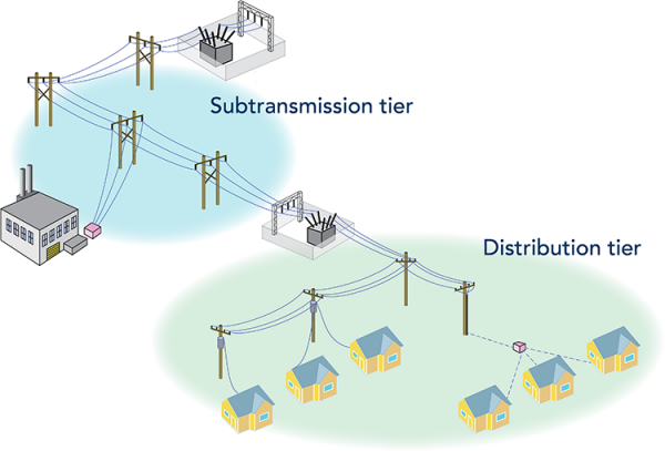
You can use tiers to organize a natural hierarchy in a domain network. Tiers typically represent ranges of pressure, voltage, or other characteristic of the network.

Network organization
Utility systems are organized into networks for the delivery of a utility resource.
An electric utility is typically organized into tiers such as transmission (high voltages), distribution (medium voltages), and secondary (low voltages). An specific feature can only participate in one tier or another. This type of configuration is modeled using a partitioned tier definition.
Gas and water utilities may manage tiers for the gathering of gas or water, transmission of gas or water over long distances, and distribution of gas or water to the consumer. Tier groups are used in the domain network to model the different sectors for a network. For example, in a gas domain network, a tier group of Distribution includes different tiers for system, pressure, and isolation. A network feature such as a device can participate in two distinct tiers in the same tier group. This type of configuration is modeled using a hierarchical tier definition.
To learn more about the network organization, see Architecture.
Tiers
Tiers are used to segregate and manage the final architectural piece of a network: subnetworks. A tier defines a collection of individual subnetworks that all share the same properties and adhere to the same restrictions. Properties are defined when you add a domain network and create tiers for the utility network. These properties determine the layout of tiers and their position relative to the rest of the tiers in a domain network.
When you define a tier, you do so by specifying subnetwork controllers, which delimit the subnetworks, to that tier. For example, a medium voltage tier in an electric distribution domain network would specify a circuit breaker device subnetwork controller. A low voltage tier would specify either the distribution transformer or network protectors subnetwork controllers. These subnetwork controller devices or junction objects are used to define the subnetworks in each tier level.
Tier rank controls the trace order of subnetworks from different tiers. This relative position, or rank, is assigned on creation to define the hierarchy of tiers. A rank of 1 represents the highest level. For example, consider an electric network with three tiers: transmission, medium voltage, and low voltage. The transmission tier has rank 1, the medium voltage tier has a rank of 2, and the low voltage tier has rank of 3. Ranking is done independently within each tier group in networks with a hierarchical tier definition.
Tier topology modeling
Tiers in a domain network have either a hierarchal or partitioned tier definition. Tiers in an electric utility typically use a partitioned tier definition. This indicates a progression of tiers (based on declining voltage levels) that are exclusive to each other. A medium voltage subnetwork is distinct from a low voltage subnetwork and does not share features.
Tiers in a gas or water utility typically use a hierarchical tier definition. This means that features in a domain network can belong to subnetworks in two different tiers. For example, a gas utility typically defines a pressure tier and valve isolation tiers with nested subnetworks. A single pressure subnetwork can have several valve isolation subnetworks.
Each tier is also assigned a topology type on creation. This is set at the tier level and pertains to all subnetworks within a tier. Domain networks with partitioned tier definitions support both mesh and radial tier topology types for subnetworks. Hierarchical domain networks only support tiers with mesh tier topology type.
To learn more about topology types, see Subnetworks.

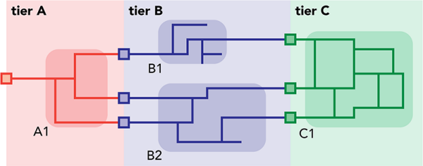
Both the mesh and radial topology types are shown in the illustration above. Tier A has a radial topology type. There is one source (at the far left) for the subnetwork labeled A1. Tier B has three sources at the left and has a topology type of radial. Subnetwork B1 has one source and has a radial topology. Subnetwork B2 has two sources and no loops, hence a radial topology. Tier C has a mesh topology. The subnetwork labeled C1 has three sources and several loops. This tier has mesh topology.