When you create or modify features that participate in a utility network, snapping, editing tools, and feature templates apply the rules and associations defined for your network.
The following sections summarize how editing tools work when you edit a utility network. To learn more about connectivity rules and associations, see the following topics:
For a basic workflow to get started, see Edit a utility network.
Junction and edge connections
When you place a network feature on a network linear feature segment or cross it with another linear network feature, the polyline is modified based on the junction and edge connectivity rules.
Junction and edge connectivity rules are based on geometric coincidence and control the types of junction assets you can connect to specific edge assets. How a polyline is modified when you make a midspan connection is listed in the following table.
| Editing scenario | Midspan connection permitted | Midspan connection not permitted |
|---|---|---|
Point feature on a polyline feature | A vertex is added to the coincident polyline. | The segment is split, and the attributes and related records are copied to the new feature. |
Polyline feature crossing a polyline feature | A vertex is added at each intersection and where an endpoint touches the polyline. | The segment is split, and the attributes and related records are copied to the new feature. |
Nonspatial objects
Junction and edge nonspatial objects can be used to model physical components contained inside network features such as strands inside a fiber cable or conductors inside an underground duct. You can also use them as container objects to contain other nested containers, features, and objects.
Nonspatial objects are stored in stand-alone tables and connected to network features using connectivity, containment, or structural associations.
To learn more, see Junction and edge objects.
Feature templates
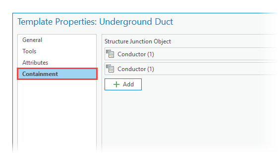
In Template Properties, the Containment tab is available when the source utility network feature layer participates in a containment association. You can add a containment template to include associated nonspatial objects with each feature the template creates.
The steps are the same as adding a table template.

Group and preset templates
Group templates can be configured to generate associations between the features they create when they contain a primary template that creates utility network features. Group template associations are limited to group features only and do not extend to the contents of preset templates assigned to the group.
Preset templates generate associations that were defined when the preset template was authored, independent of any group settings. This is true when you use them as component templates in a group template or as stand-alone templates.
For example, a group template with a primary template for a medium-voltage line and a feature template for a medium-voltage attachment as the snapping device can be configured to generate associations using these features.
If the group template in this example also contains a preset template for a transformer bank, the transformer bank components are placed in a map with the associations defined for them when the preset template was authored.
For steps to create a group template, see Create a group template.
Snapping
When you add or move a network feature, snap settings automatically change to settings that conform to junction and edge connectivity rules. You can turn snapping off, but you cannot change the layers or features to which you are snapping.
Tip:
When you create features, press T to view the snappable elements of a feature with respect to the connectivity rules.
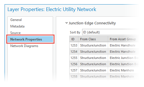
To view connectivity rules, right-click the network in the Contents pane, click Properties  , and click the Network Properties tab.
View and edit network attributes
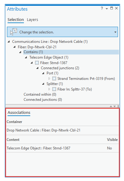
To view and edit utility network attributes in the Attributes pane, select the feature and expand the selection in the tree view. Associations appear below the selected feature or object and report the total number of associated subfeatures or subobjects.

| Editing scenario | Workflow | Command or tool |
|---|---|---|
View From/To network information. | In the tree view, click a junction or edge object. | The Associations tab |
Add nonspatial objects to an existing container object. | In the tree view, right-click the container. | Add New To Container |
Remove a nonspatial object from a container feature. | In the tree view, right-click the nonspatial object. | Remove Association |
Selections
Editing tools filter selection sets based on the type of edits the tool performs. To avoid unexpected results when selecting nonspatial objects, for example, in a utility network attribute table, deactivate the current editing tool before executing a command.
A toast notification alerts you when an editing tool is actively filtering a selection. To restore the selection to its unfiltered state, deactivate the current tool by pressing the Esc key or clicking the back arrow in the Modify Features pane.
Move network features
When you use Move  to move a network feature, coincident features and features associated as container objects and structural attachments also move. For example, moving a duct bank also moves its contents, or moving a pole also moves a transformer attached to it.
Features that share a coincident endpoint, edge, or vertex, when midspan connections are permitted, are also edited. All coincident features move with the selected feature and linear features are stretched so that the visible feature topology remains contiguous.
Editing linear assets with tools such as Vertices  also edits other network features sharing the same x,y,z location and displays a rubber band line that stretches dynamically when you move a vertex.
Note:
Utility networks use network topology to maintain connectivity among features and do not participate in map topology. Network topology enables you to trace a network and identify connected features, determine flow characteristics of a commodity such as water or electricity based on feature attributes, and perform other analytic operations.
To learn more, see About network topology.
Split network features
When you use the Split tool  to split a utility network line feature, the resulting features are connected with a system junction feature at the location of the split. Asset types constrained by attribute domains are determined by the domain split policy defined for the utility network.
For example, container contents and associated attribute assignments are maintained based on the containment split policy defined for structure line feature classes.
To learn more, see Associations.
 .
.