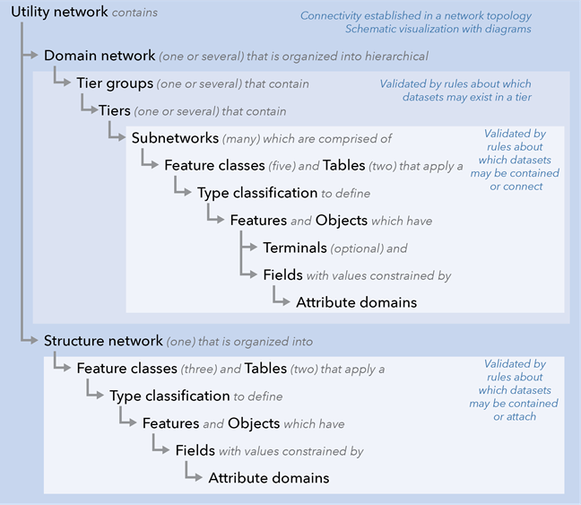
A utility network allows you to model how all the components of a utility system are connected, intelligently handle dense collections of utility features, and perform hierarchical tracing analysis of a network. The following is a structural overview of how a utility network is organized:

- A preconfigured set of feature classes is created for you when you create a utility network. First, three feature classes are created to model the structural features that support the various types of utility features. These feature classes are collectively called the structure network. A structure network does not have any resources (such as water or electricity) flowing through it; however, the structure network can contain and support other features that are part of the resource-delivering network.
- A utility network contains one or more domain networks. These consist of standardized classes created during operations to create and add a domain network that are configured to model each of the systems operated by a utility.
- In a domain network, all the features are first organized into tier groups and tiers. Tiers model the hierarchy of how the network delivers a resource such as natural gas, electricity, or water. A tier typically represents a pressure or voltage level. For example, an electric distribution system can be divided into subtransmission, medium-voltage, and low-voltage levels, and some type of analysis should be performed in only one of these hierarchical levels. A tier can also represent parts of the network that can be isolated from one another, such as a valve isolation zone in a pressure-based system. Tiers are useful because they allow you to constrain the valid feature types for each tier, and they also define the range of network tracing analysis.
- The flow of resources in a utility is controlled by devices such as valves and switches. The extent of resource delivery at a given time is called a subnetwork, and this corresponds to a pressure zone for gas and water utilities or circuits for electric utilities. With a utility network, subnetworks are discovered on demand by starting at the subnetwork controller of the delivered resource and tracing through the network until closed valves, open electric switches, or consumption points are reached.
- All of the features in subnetworks are grouped into five feature classes and two tables in a domain network. These contain the features for subnetlines, devices, device assemblies, lines, and junctions where parts of the network connect.
- When adding features, you have enhanced capabilities for defining how utility features are connected. While snapping features or line ends to the same location will automatically connect features, you can also specify that devices separated on the map be logically connected. This type of connectivity is especially useful for dense areas of your utility maps.
- Many key utility devices are enclosed in cabinets, vaults, or yards or grouped into banks. With a utility network, you can group these internal features into container features so that the container can be shown on the map without the clutter of all the internal features. Internal features can be viewed on demand in a map or in a diagram view.
- A rich type classification system is built into a utility network to help represent every type of utility feature. This is done using the ASSETGROUP and ASSETTYPE fields to provide a classification in the domain network classes with the use of subtypes and attribute domain assignment at the subtype level. Utility network operations—such as specifying network connectivity rules, symbolizing features, tracing, and many more—are configured on network feature classes using this classification system. This allows a utility network to define a fine-grained classification using a compact number of feature classes.
- Some utility network features enable terminals to be modeled. Terminals can be defined on a device feature class or junction object table when it is important to track the different ports (such as high-side and low-side of service). Terminals provide more accurate tracing because you can control the valid paths for a resource. You can also define which terminal on a feature is the subnetwork controller. Terminals are also necessary for many external analytic software packages.
- Engineers at a utility often prefer a schematic view of a utility system to augment the map view. Schematic capabilities are built into the utility network and are called diagrams. You have considerable flexibility in configuring which utility features are depicted in a diagram as well as selecting algorithms for generating the diagram.
- Utilities need to know which devices are attached to structures such as poles and vaults. A utility network allows you to define structural attachments so that you can generate inventory lists for areas and subnetworks, locate field assets by structure identifiers, and attach multiple types of utility features from different services (such as electric and telecommunication) to a common structure (such as a pole). You will define rules for the domain network features that can be attached to structural features. These structural attachments can be viewed on demand on the map or in the diagram view.